Resource Tower

a resource tower and resource technology, applied in the field of resource towers, can solve the problems of limiting the supply of hsub>2 /sub>hydrogen in the resource tower

Inactive Publication Date: 2017-02-02
REILLY THOMAS MICHAEL
View PDF5 Cites 3 Cited by
  • Summary
  • Abstract
  • Description
  • Claims
  • Application Information

AI Technical Summary

Benefits of technology

[0027]Gas flow electricity production is key to the Resource Tower producing a net abundance of electricity. This demand for maximum electricity production is illustrated in the preferred apparatus configuration by including electricity generation at five points of energy extraction provided a phase of water or its elements as facilitated by Resource Tower. The Resource Tower maximizes the natural properties of each phase or element of water to extract the greatest energy potential at the least energy cost. On such is that gases can be easily and readily elevated to great heights with little, if any, energy penalty. Under pressure created by continuous production of large volumes of gas converted from liquid water, added heat to excite and further expand the pressure and flow rate of the gases, and by the negative pressure drawing the gas forward by consumption the hydrogen and oxygen gases provide another energy source for electricity production. Electricity is consumed by the water electrolyzer to form hydrogen and oxygen gases when in turn create a gas flow for the reciprocating electricity generators, gas flow generators, fuel cell electrochemical reaction from which emerge electricity, heat, and water. Indirectly by conversion of heat and water byproducts of the fuel cells to generate electricity by water vapor or steam expansion and then by the mass of water falling under the acceleration of gravity also contribute to the net production of Resource Tower electricity. The Resource Tower height depends on number of electricity generators needed in the path of gas flows and water flow to overcome the penalty of water electrolysis and the demands of the village and communities it is deployed to support.

Problems solved by technology

The supply of H2 hydrogen is the limiting factor of the Resource Tower.

Method used


Image

  • Resource Tower
  • Resource Tower
  • Resource Tower

Examples


examples and narrative description

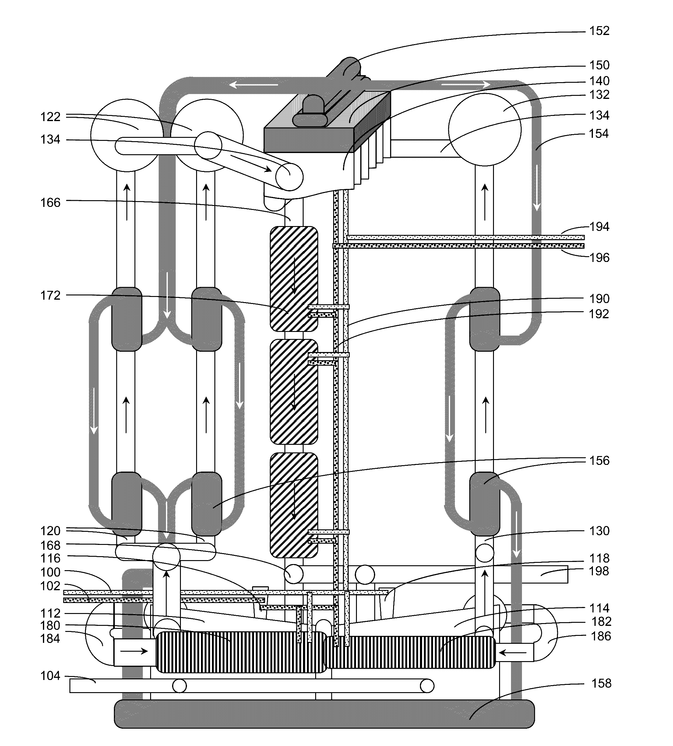
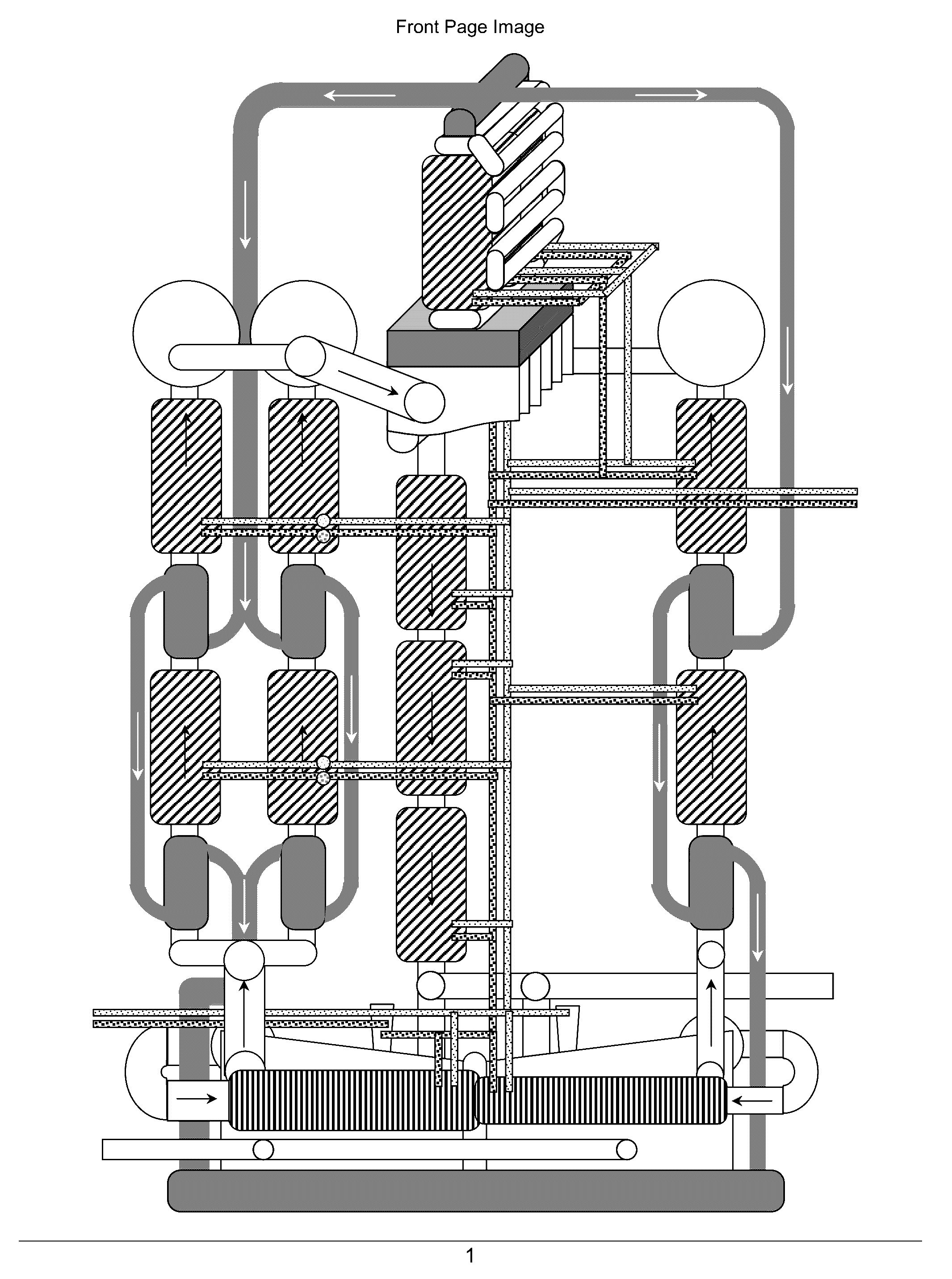
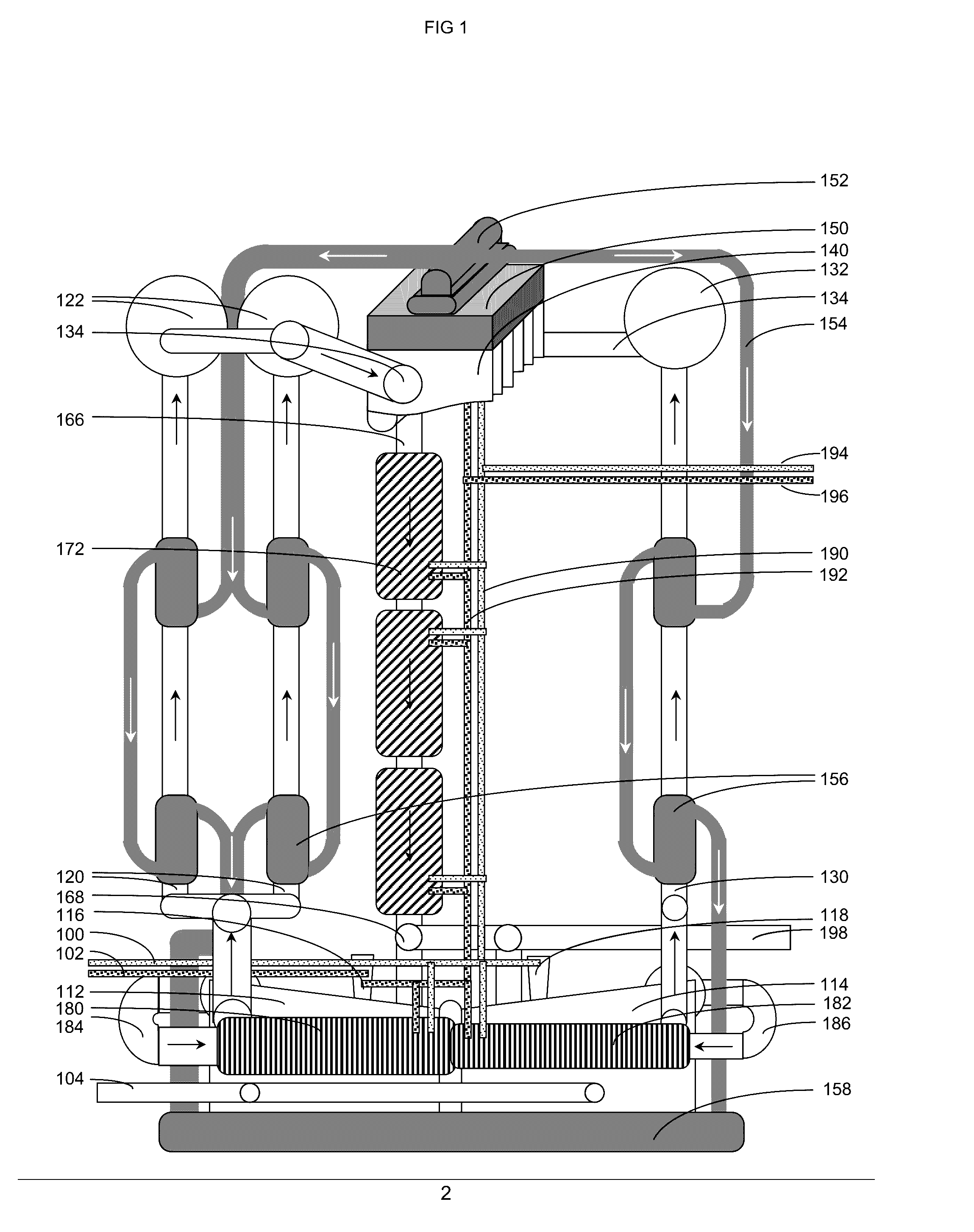
[0082]The Resource Tower is substantially constructed to support one or more H2 hydrogen gas to O2 oxygen gas reactors. Said reactors may include reciprocating combustion engines, turbine combustion engines, fuel cells, or other mechanism capable of converting elements of water from hydrogen gas and oxygen gas (as a byproduct of H2 production or from air) into liquid water while simultaneously producing an electric energy output. As a best mode, one or more fuel cells are used to produce electricity, heat, and water. As water having mass with capability of doing work is formed at a height, there is potential for additional energy production with water falling through electricity generators. The height of the Resource Tower is sufficient that the combined electrical energy produced from the fuel cell and fall of water is equivalent or greater than the energy required to operate controls and produce more hydrogen gas. In a closed system at near equilibrium, the energy tower is capable...


PUM

PropertyMeasurementUnit
post-reaction thermal energyaaaaaaaaaa
thermal energyaaaaaaaaaa
thermalaaaaaaaaaa

Abstract

Invented is a Resource Tower that uses water electrolysis to separate out its elemental and purified H2 hydrogen gas and O2 oxygen gas. These gases form a pressurized flow for electricity generation for distribution and transport to heights atop the Resource Tower. Core advancements of this invention are the use of fuel cells at the top of the Resource Tower to electrochemically combine hydrogen gas and oxygen gas to produce electricity, heat, and water. The Resource Tower distributes the electricity, converts heat and water to steam to generate additional electricity for distribution, and ultimately coalesces the steam back to water at a height. The water that falls under acceleration of gravity from atop the Resource Tower is used to generate additional electricity for distribution. In addition to multiple sites of electricity generation for distribution, the purity of hydrogen gas and oxygen gas from water electrolysis is retained and the water resulting from the Resource Tower is purified and potable for distribution.

Description

CROSS-REFERENCE TO RELATED APPLICATIONS[0001]Not Applicable.STATEMENT REGARDING FEDERALLY SPONSORED RESEARCH OR DEVELOPMENT[0002]Not applicable.REFERENCE TO A SEQUENCE LISTING[0003]Not Applicable.BACKGROUND OF THE INVENTION[0004]Field of the Invention[0005]Core to the invention is water electrolysis for purified H2 hydrogen gas and O2 Oxygen gas flowing upward past electricity generators to a height where the gases are electrochemically combined in fuel cells to form electricity, heat and indirect electricity, and water that flows under gravity from the height of the Resource Tower past electricity generators, and also delivers purified water, or resources from the tower.[0006]Problem Statement[0007]There is continued and growing concern about a lack of available and sustainable energy from all energy sources. Electricity is a dominate form of energy produced because of its versatility, current infrastructure, tailorability, and many other favorable properties. The production of ele...

Claims


Application Information

Patent Timeline
Patent Type & Authority Applications(United States)
IPC IPC(8): H01M8/0656H01M16/00H02K35/02F01K15/00H02K7/18
CPCH01M8/0656F01K15/00H02K7/1823H02K35/02H01M2250/10Y10S74/09H02K53/00H02N11/008H01M2250/402H01M16/003F22B27/00Y02B90/10Y02E60/16Y02E60/50Y02W10/33Y02W10/37
Inventor REILLY, THOMAS MICHAEL
Owner REILLY THOMAS MICHAEL
Why Eureka
Try Eureka