Transmitarray unit cell for a reconfigurable antenna

a technology of transmit antenna and unit cell, which is applied in the structure of radiating elements, particular array feeding systems, antennas, etc., can solve the problems of affecting the radiation diagram of the transmit antenna, affecting the performance of the unit cell, and forming of switches thus becoming a problem, so as to achieve the effect of reducing dielectric losses

Active Publication Date: 2017-02-02
COMMISSARIAT A LENERGIE ATOMIQUE ET AUX ENERGIES ALTERNATIVES
View PDF6 Cites 22 Cited by
  • Summary
  • Abstract
  • Description
  • Claims
  • Application Information

AI Technical Summary

Benefits of technology

[0073]Thus, such a resistivity enables to decrease dielectric losses as compared with a standard substrate for radio (RF) applications.

Problems solved by technology

The forming of the switches thus becomes a problem due to the small dimensions of the transmit antenna.
The switches, arranged inside of a package and placed on the second surface of the second printed circuit board, are then likely to significantly degrade the unit cell performances.
Indeed, the package of each switch tends to disturb the close environment of the first and second radiation surfaces, and thereby affects the radiation diagram of the transmit antenna.
Such electric connections make the switch integration more complex, by taking up a non-negligible space in the separation area, which has a small size.

Method used


Image

  • Transmitarray unit cell for a reconfigurable antenna
  • Transmitarray unit cell for a reconfigurable antenna
  • Transmitarray unit cell for a reconfigurable antenna

Examples


Embodiment Construction

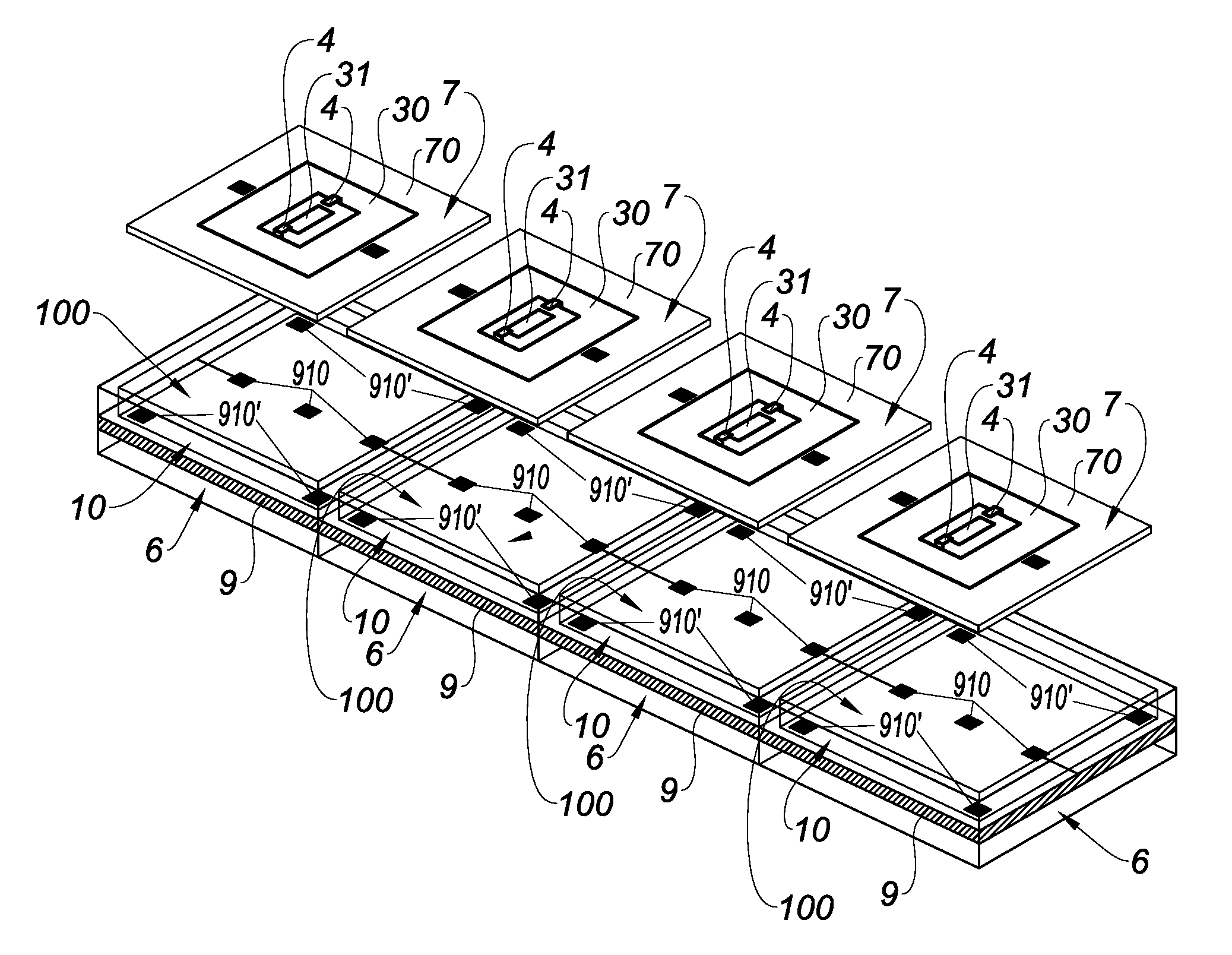
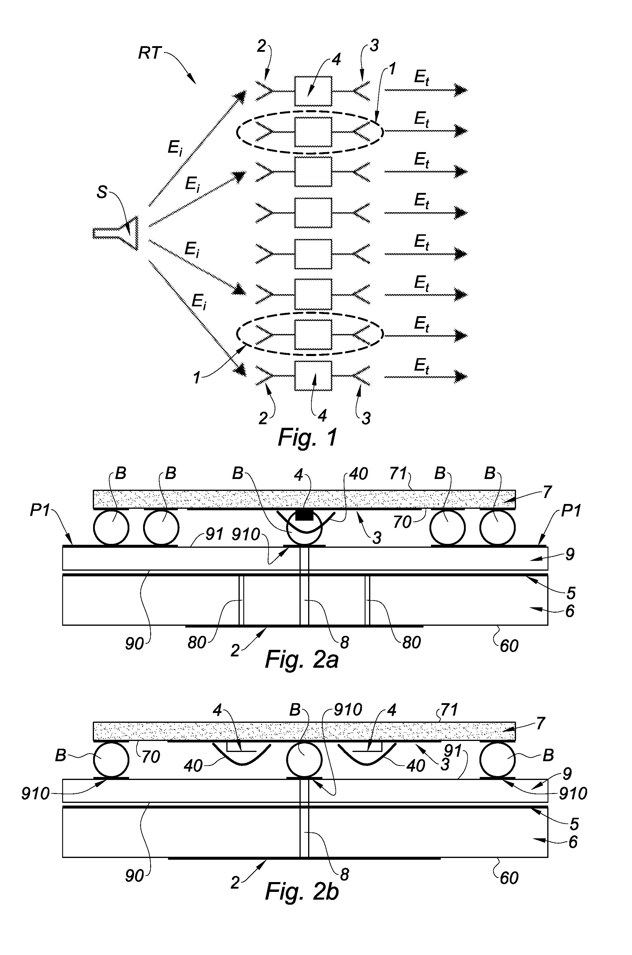
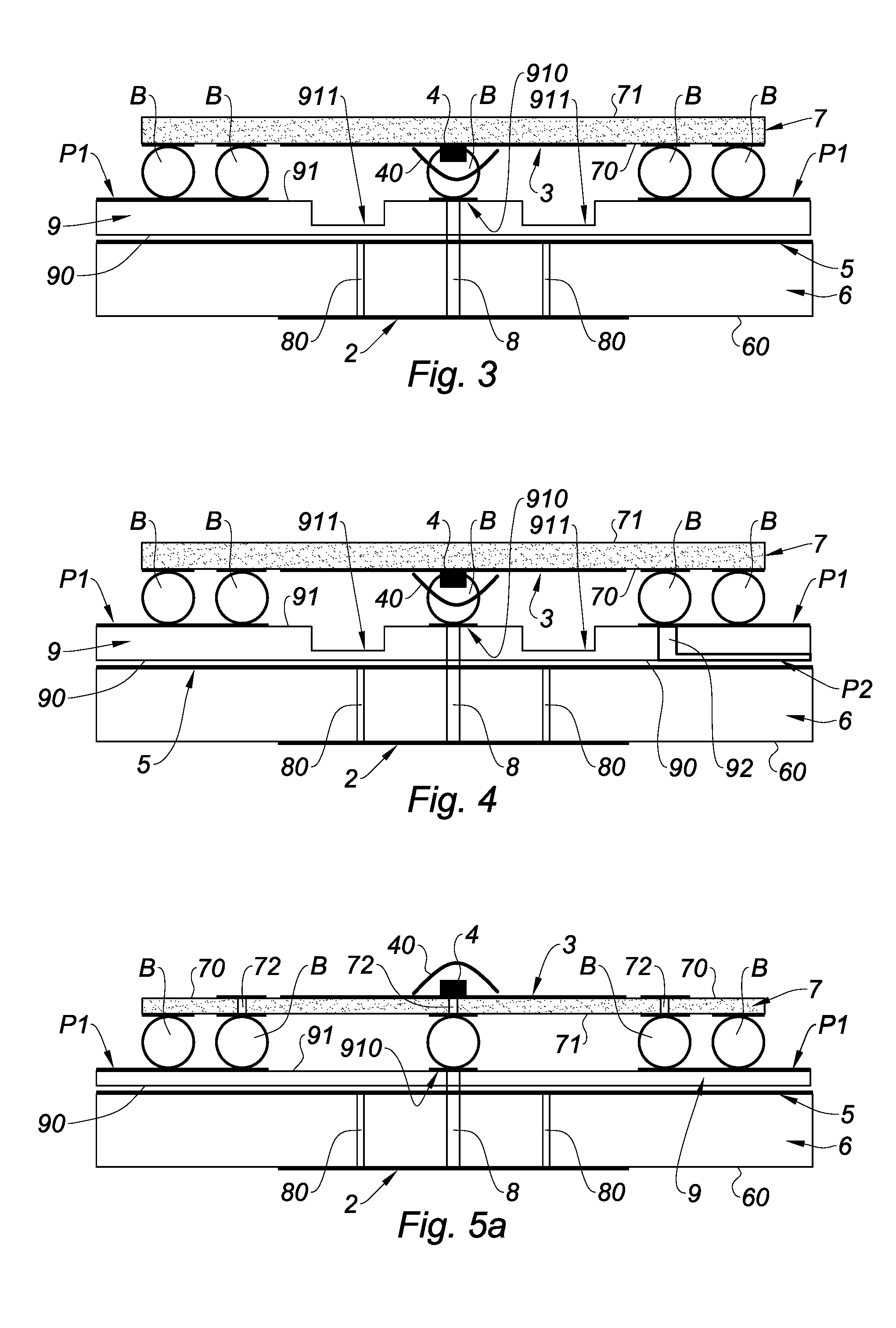
[0085]For the different embodiments, the same references will be used for identical elements or elements performing the same function, to simplify the description. The technical characteristics described hereafter for different embodiments are to be considered separately or according to any technically possible combination.

[0086]FIGS. 1 to 7 illustrate a unit cell 1 of a transmitarray RT for an antenna reconfigurable at an operating frequency, preferably in the range from 30 GHz to 110 GHz.

[0087]Unit cell 1 comprises:

[0088]a receive patch antenna 2, intended to receive an incident wave Ei;

[0089]a transmit patch antenna 3 intended to transmit the incident wave Ei with a phase shift (the phase-shifted transmitted wave Et being illustrated in FIG. 1), and comprising first and second radiation surfaces 30, 31 separated from each other by a separation area ZS (clearly apparent in FIG. 6) to be electrically isolated, transmit antenna 3 and receive antenna 2 being electrically connected to...


PUM


Abstract

Unit cell including a receive antenna, a transmit antenna, and including first and second radiation surfaces separated from each other by a separation area, a phase-shift circuit comprising switches, each having an on, respectively off, state, wherein the corresponding switch allows, respectively blocks, the flowing of a current between the first and second radiation surfaces; a ground plane; a first printed circuit board including a first surface provided with the receive antenna, and a second opposite surface provided with the ground plane; a wafer of a semiconductor material including a first surface provide with first and second radiation surfaces and wherein the switches are formed in the separation area, monolithically with the transmit antenna.

Description

TECHNICAL FIELD[0001]The present invention relates to a transmitarray unit cell for an antenna reconfigurable at an operating frequency, preferably in the range from 30 GHz to 110 GHz. The present invention also relates to a reconfigurable antenna comprising a transmitarray comprising such unit cells.[0002]“Reconfigurable” means that at least one characteristic of the antenna can be modified during its lifetime, after the manufacturing thereof. The characteristics which can generally be modified are the frequency response, the radiation diagram (also called beam), and the polarization. The reconfiguration of the frequency response covers different functionalities such as frequency switching, frequency tuning, bandwidth variation, frequency filtering, etc. The reconfiguration of the radiation diagram covers different functionalities such as beam steering, beamwidth (that is, the concentration of the radiation along a specific direction), spatial filtering, beam or multibeam (for exam...

Claims


Application Information

Patent Timeline
Patent Type & Authority Applications(United States)
IPC IPC(8): H01Q9/04H01Q1/38H01Q1/48
CPCH01Q9/0407H01Q1/38H01Q1/48H01Q1/2283H01Q3/46H01Q21/0018H01Q21/0093H01Q23/00
Inventor CLEMENTE, ANTONIODUSSOPT, LAURENTREIG, BRUNO
Owner COMMISSARIAT A LENERGIE ATOMIQUE ET AUX ENERGIES ALTERNATIVES
Why Eureka
Try Eureka