Rotor, and Permanent-Magnet-Type Rotational Electric Machine, Electric Drive System, and Electric Vehicle Which are Provided with Said Rotor

Active Publication Date: 2017-02-02
HITACHI ASTEMO LTD
View PDF6 Cites 2 Cited by
  • Summary
  • Abstract
  • Description
  • Claims
  • Application Information

AI Technical Summary

Benefits of technology

The present invention introduces a permanent magnet type rotational electric machine that can help the engine to achieve better torque and power generation, even at high speeds. This machine is designed to ensure peak torque or electric power generation torque for assisting the engine, and it can maintain superior performance even when using rare earth-less magnets.

Problems solved by technology

However, there is a high risk of resource depletion of the dysprosium, and therefore, application of rare earth-less magnets having less amounts of readily available permanent magnet materials, e.g., ferrite magnets and dysprosium, applied therein, is being reviewed from the perspective of avoiding risks.

Method used


Image

  • Rotor, and Permanent-Magnet-Type Rotational Electric Machine, Electric Drive System, and Electric Vehicle Which are Provided with Said Rotor
  • Rotor, and Permanent-Magnet-Type Rotational Electric Machine, Electric Drive System, and Electric Vehicle Which are Provided with Said Rotor
  • Rotor, and Permanent-Magnet-Type Rotational Electric Machine, Electric Drive System, and Electric Vehicle Which are Provided with Said Rotor

Examples


first embodiment

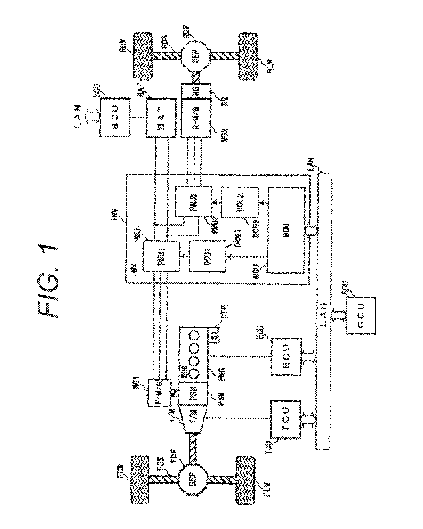
[0021]First, a configuration of a vehicle to which the rotational electric machine of the present embodiment is applied will be explained with reference to FIG. 1. In the present embodiment, a hybrid electric vehicle having two different power sources will be explained as an example.

[0022]The hybrid electric vehicle according to the present embodiment is a four wheel drive type configured so that front wheels FLW, FRW are driven by an engine ENG which is an internal combustion engine and a rotational electric machine MG1, and rear wheels RLW, RRW are driven by a rotational electric machine MG2.

[0023]In the present embodiment, the case where the front wheels WFLW, FRW are driven by the engine ENG and the rotational electric machine MG1, and the rear wheels RLW, RRW are driven by the rotational electric machine MG2 will be explained. Alternatively, the front wheels WFLW, FRW may be driven by the rotational electric machine MG1, and the rear wheels RLW, RRW may be driven by the engine ...

second embodiment

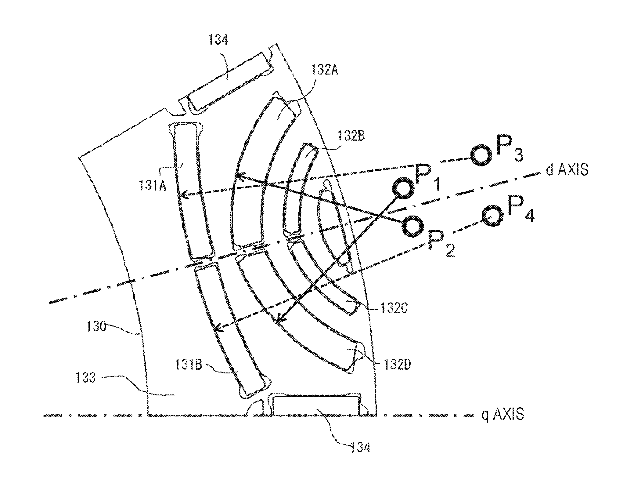
[0079]FIG. 7 illustrates a partially enlarged view of a rotator cross section illustrating another embodiment of the present invention, and the same objects as those in FIG. 5 are denoted with the same reference numerals.

[0080]The drawing in FIG. 7 is different from FIG. 5 in that the third permanent magnet 134 is eliminated, and the configuration is made with only a first permanent magnet pair 131 and a second permanent magnet pair 132.

[0081]According to this configuration, the torque characteristics are lower than that in FIG. 5, but in contrast to the configuration based on the design concept that the magnet magnetic flux is mechanically concentrated on d axis, an effect of improving the amount of magnetic flux of the permanent magnet can be obtained, and in addition, the number of components can be reduced, and a space into which a magnet is inserted in a q axis portion is made with a magnetic steel sheet, and therefore, the mechanical strength against the centrifugal force of t...


PUM


Abstract

A permanent magnet type rotational electric machine for an electric vehicle capable of ensuring an electric power generation torque or a peak torque instantaneously assisting a torque of an engine even by using a rare earth-less magnet and also capable of ensuring characteristics for high speed driving is provided. A rotator includes permanent magnets of which at least one side in an axial direction cross section is formed in an arc shape, and includes a plurality of permanent magnets, wherein where a center axis of a magnetic pole is denoted as d axis, and an axis that is 90 degrees from the d axis in an electrical angle is denoted as q axis, the rotator for the permanent magnet type rotational electric machine includes a first permanent magnet pair in which a line connecting a center point of the arc and the arc does not cross the d axis, and a second permanent magnet pair in which the line crosses the d axis.

Description

TECHNICAL FIELD[0001]The present invention relates to a rotator, and a permanent magnet type rotational electric machine, an electric drive system, and an electric vehicle having the same.BACKGROUND ART[0002]Rotational electric machines for vehicles, such as driving motors of hybrid electric vehicles and the like require acceleration performance such as startup, overtaking, and the like, and therefore, motors are required to have a high instantaneous peak torque. In a case of permanent magnet type rotational electric machines used for the purpose of automobiles, rare earth magnets having a high magnetic energy product are employed as permanent magnets used for the rotators generating this peak torque. In this case, dysprosium is added to the rare earth magnet used for the purpose of automobiles in order to withstand a high temperature environment. However, there is a high risk of resource depletion of the dysprosium, and therefore, application of rare earth-less magnets having less ...

Claims


Application Information

Patent Timeline
IPC IPC(8): H02K1/27H02K3/12B60L50/15B60L50/16
CPCH02K3/12H02K1/2766H02K2213/03B60L3/0061B60L15/007B60L2210/40B60L2240/12B60L2240/421B60L2240/423B60L2240/425B60L2240/441B60L2240/443B60L2260/28B60L2220/50B60L50/61B60L50/16B60L58/21Y02T10/62Y02T10/64Y02T10/70Y02T10/7072Y02T10/72
Inventor KIKUCHI, SATOSHI
Owner HITACHI ASTEMO LTD
Why Eureka
Try Eureka