Complex Coil And Manufacturing Techniques

a manufacturing technique and complex coil technology, applied in the field of complex coils and manufacturing techniques, can solve the problems of time-consuming process, difficult to manufacture coils of various sizes, and difficulty in quickly and efficiently occlude the target spa

Active Publication Date: 2017-02-09
TERUMO KK
View PDF1 Cites 186 Cited by
  • Summary
  • Abstract
  • Description
  • Claims
  • Application Information

AI Technical Summary

Benefits of technology

[0018]In one embodiment, the mandrel includes one or more winding sections which are located in a first plane, and one or more regions which are located in a second plane.
[0019]In one embodiment, the mandrel includes two or more winding sections which are located in a first plane, and two or more regions which are located in a second plane.
[0020]In one embodiment, the mandrel includes two or more winding sections which are located in a first plane, and two or more regions which are located in a second plane, where the second plane is offset by about 60 degrees from the first plane.
[0021]In one embodiment, the mandrel comprises one or more repeating sections.
[0022]A process and / or method to wind an embolic coil on a mandrel is described. In one embodiment, the process and / or method involves winding a coil over a mandrel with one or more repeating sections. In another embodiment, the process and / or method involves winding a coil over a mandrel with one or more repeating sections and cutting the coil to produce two or more identical sections.

Problems solved by technology

Due to the complex geometries associated with the vasculature, it is often difficult to have a coil that can quickly and efficiently occlude the target space.
This can often be a time consuming process.
Manufacturing coils of various sizes can be challenging since the coils are often individually wound on different mandrels or on different regions of a mandrel in order to produce coils of various sizes and / or shapes.

Method used


Image

  • Complex Coil And Manufacturing Techniques
  • Complex Coil And Manufacturing Techniques
  • Complex Coil And Manufacturing Techniques

Examples


Embodiment Construction

[0030]Specific embodiments of the invention will now be described with reference to the accompanying drawings. This invention may, however, be embodied in many different forms and should not be construed as limited to the embodiments set forth herein; rather, these embodiments are provided so that this disclosure will be thorough and complete, and will fully convey the scope of the invention to those skilled in the art. The terminology used in the detailed description of the embodiments illustrated in the accompanying drawings is not intended to be limiting of the invention. In the drawings, like numbers refer to like elements.

[0031]U.S. Pat. Nos. 9,089,405 and 8,066,036 and U.S. Pub. No. 2011 / 0184455 disclose complex coil embodiments and manufacturing techniques, and are hereby incorporated by reference in their entirety.

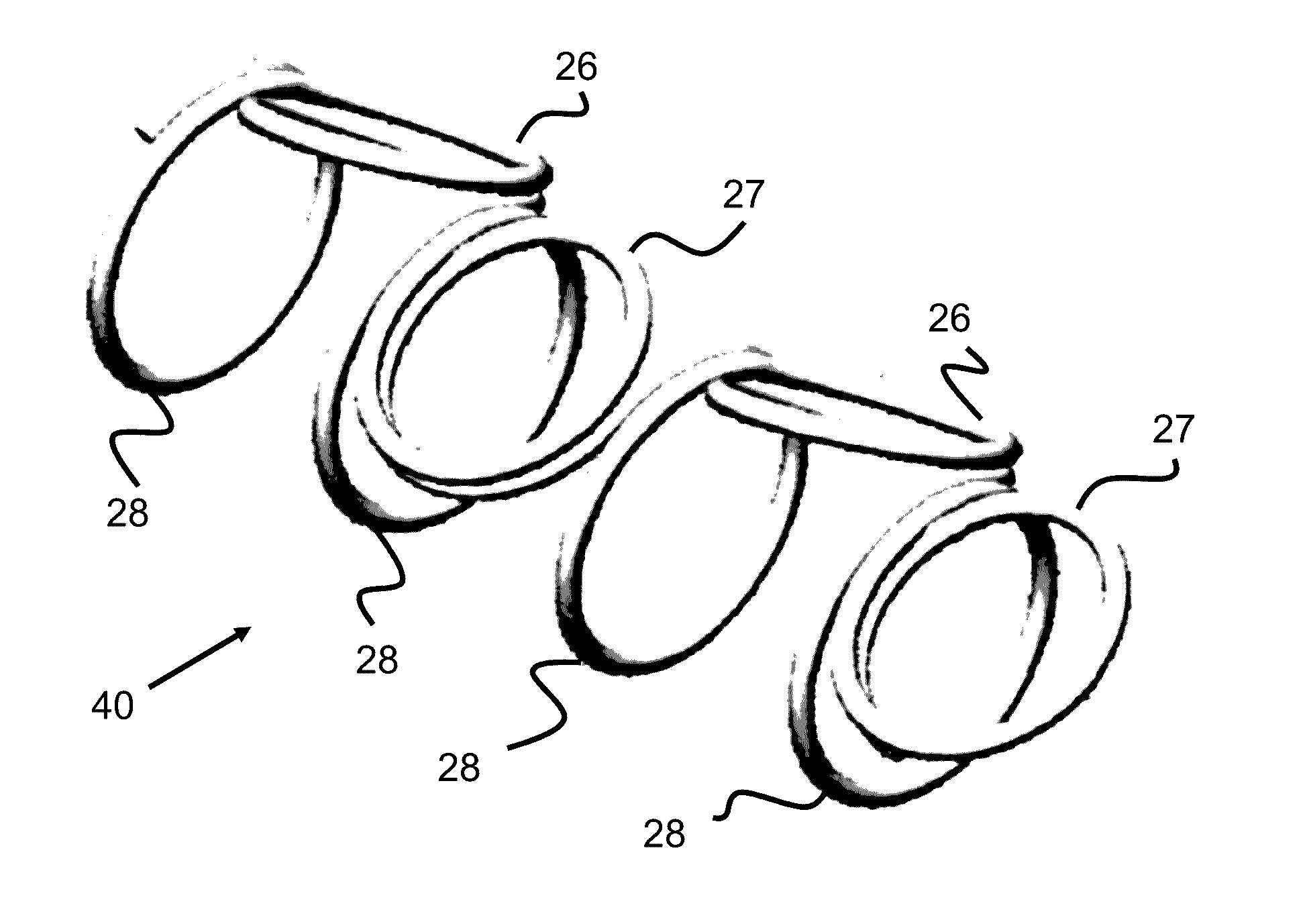
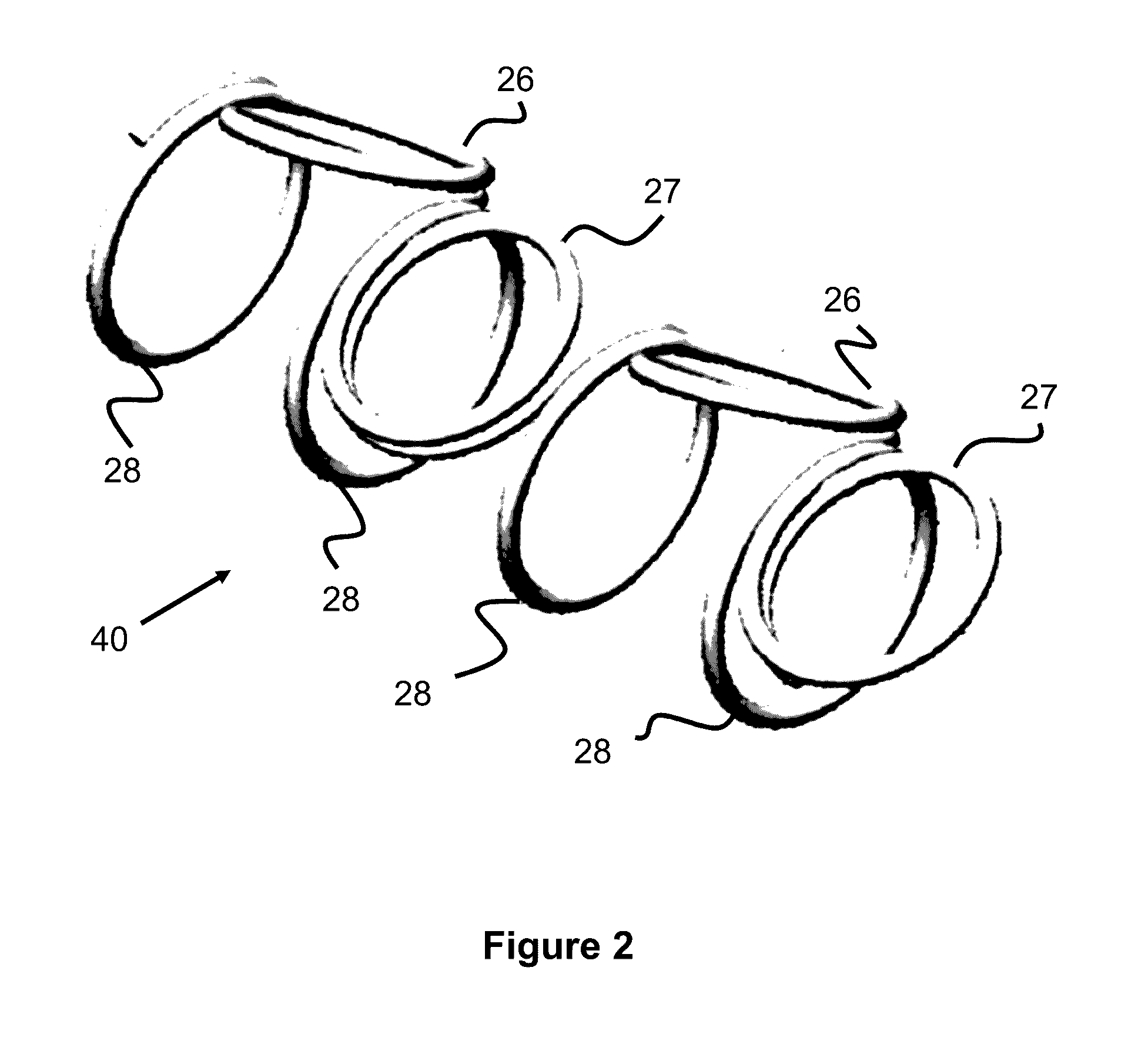
[0032]Embolic coils are used for occlusive purposes in the vasculature for various reasons, such as occluding aneurysms, atrial septal defects, patent foramen oval...


PUM


Abstract

An embolic coil which can be used for occlusive purposes in the vasculature is described. A mandrel for manufacturing a coiled structure, and method/process for manufacturing a coiled structure is described.

Description

RELATED APPLICATIONS[0001]This application claims priority to U.S. Provisional Application Ser. No. 62 / 202,649 filed Aug. 7, 2015 entitled Complex Coil, which is hereby incorporated herein by reference in its entirety.BACKGROUND OF THE INVENTION[0002]An apparatus and method for embolizing a target site in the vasculature is described.[0003]Vessel occlusion is often necessary in a variety of cases including, but not limited to, treatment of aneurysms, atrial septal defects, patent foramen ovale, left atrial appendage occlusion, patent ductus arteriosus, fistula, arterio-venous malformations, fallopian tube occlusion for the purposes of sterilization, and occlusion in the peripheral vasculature. One method of vessel occlusion involves filling the vessel, malformation, or aneurysm with coils for the purposes of embolization. Such coils may be referred to as embolic coils. Due to the complex geometries associated with the vasculature, it is often difficult to have a coil that can quickl...

Claims


Application Information

Patent Timeline
Patent Type & Authority Applications(United States)
IPC IPC(8): A61B17/12A61F6/22
CPCA61B17/12145A61B17/12113A61F6/22A61B2017/00526A61B2017/00898A61B2017/00641A61B2017/00632A61B2017/00867A61B2090/3966
Inventor MORITA, HIDEO
Owner TERUMO KK
Why Eureka
Try Eureka