
Cell culture device and method of manufacturing the same

a cell culture membrane and cell technology, applied in the field of cell culture membrane devices and, can solve the problems of affecting cell culture, deformation of the cell culture membrane in the neighborhood, and damage to the flatness of the cell culture membrane on the culture surface, so as to suppress the reduction of the strength of the cell culture membrane, suppress the elution, and enhance the fixation

Active Publication Date: 2017-02-09
TOYODA GOSEI CO LTD +1
View PDF7 Cites 4 Cited by
  • Summary
  • Abstract
  • Description
  • Claims
  • Application Information

AI Technical Summary

Benefits of technology

The cell culture device described in this patent improves the strength of the connection between the cell culture membrane and the substrate, while also preventing substances from leaching into the culture solution during cell culture. This is achieved by using a thermosetting resin for the cell culture membrane, which maintains its shape and prevents deformation when fixed to the substrate. This ensures the membrane's accuracy and reduces variability in the cell culture conditions. Overall, this device provides a more robust and reliable tool for cell culture research.

Problems solved by technology

In this method, however, an additive included in the adhesive tape or the adhesive agent is likely to be eluted in a culture solution and affect cell culture.
This is likely to cause deformation of the cell culture membrane in the neighborhood of the welded part (for example, stretch or wrinkle) and damage the flatness on a culture surface of the cell culture membrane.
In the cell culture membrane, reducing the flatness on the culture surface is likely to affect cultured cells and provide noise of the culture condition during cell culture.
This is likely to fail to keep the culture conditions sufficiently constant and thereby cause a problem, such as variability in results of analysis.

Method used


Image

  • Cell culture device and method of manufacturing the same
  • Cell culture device and method of manufacturing the same
  • Cell culture device and method of manufacturing the same

Examples


first embodiment

A. First Embodiment

[0040]A-1. General Configuration of Cell Culture Device

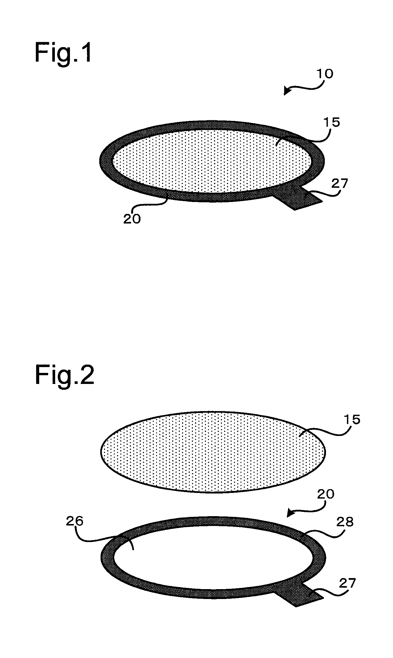
[0041]FIG. 1 is a perspective view schematically illustrating the configuration of a cell culture device 10 according to a first embodiment. FIG. 2 is an exploded perspective view illustrating assembly of the cell culture device 10. The cell culture device 10 includes a cell culture membrane 15 and a substrate 20.

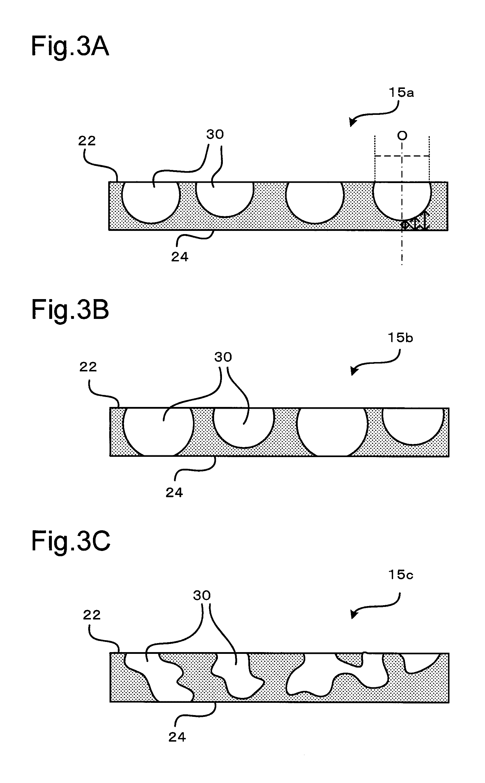
[0042]The cell culture membrane 15 is a porous membrane in an approximately circular shape. As shown in FIG. 2, the substrate 20 is formed from a ring-shaped sheet having a circular hole 26 at the center. The hole 26 of the substrate 20 is formed to have a smaller outer diameter than the outer diameter of the cell culture membrane 15. The substrate 20 is formed to have an outer diameter that is approximately equal to the outer diameter of the cell culture membrane 15. In the cell culture device 10 of the embodiment, the cell culture membrane 15 is placed on the substrate 20 to close the hole 26, and t...

second embodiment

B. Second Embodiment

[0076]FIG. 6 is an exploded perspective view illustrating the configuration of a cell culture device 10 according to a second embodiment. In the second embodiment, the like components to those of the first embodiment are expressed by the like reference numbers and are not described in detail. The cell culture device 10 of the second embodiment has the similar appearance to that of the cell culture device 10 of the first embodiment shown in FIG. 1 but differs from the cell culture device 10 of the first embodiment by providing substrate portions 20a and 20b as the substrate. More specifically, the cell culture device 10 of the second embodiment includes a substrate portion 20b that consists of a frame body 28 and is made from a thermoplastic resin, in addition to a substrate portion 20a that is the same as the substrate 20 in the cell culture device 10 shown in FIGS. 1 and 2, and the cell culture membrane 15 is placed between the pair of substrate portions 20a and...

third embodiment

C. Third Embodiment

[0083]FIG. 8 is an exploded perspective view illustrating the configuration of a cell culture device 110 according to a third embodiment. The cell culture device 110 of the third embodiment includes the cell culture device 10 of the first embodiment or the second embodiment. In the third embodiment, the like components to those of the first embodiment are expressed by the like reference numbers and are not described in detail. In the description of this embodiment, the cell culture device 10 of the first embodiment or the second embodiment is called cell culture membrane structure 10.

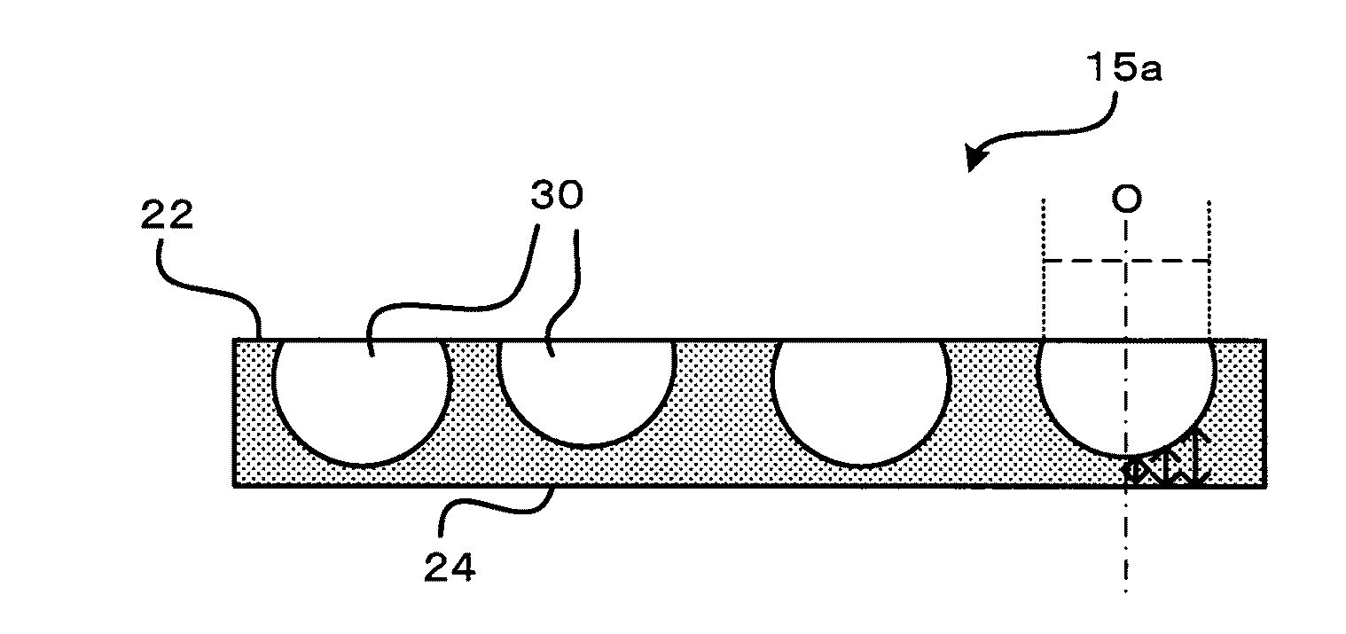
[0084]In a cell culture membrane 15 included in the cell culture membrane structure 10 of the third embodiment, at least part of pores 30 are formed as through holes. The cell culture device 110 of the third embodiment is a device used to seed cells on the respective surfaces of the cell culture membrane 15 for two-sided culture. The cell culture device 110 includes an outer cylinder ...


PUM

PropertyMeasurementUnit
Pore sizeaaaaaaaaaa
Thicknessaaaaaaaaaa
Thicknessaaaaaaaaaa

Abstract

A cell culture device comprises a cell culture membrane and a substrate fixed to the cell culture membrane. The cell culture membrane is made from a thermosetting resin and has a plurality of pores that are open to at least one surface including a surface on a side that is in contact with the substrate. The substrate is made from a thermoplastic resin. In a contact region between the cell culture membrane and the substrate, part of the substrate is extended to form bulges in the pores of the cell culture membrane that are open in the contact region. This configuration suppresses reduction of the strength of the cell culture membrane and reduction of the flatness of the cell culture membrane (membrane accuracy) in the cell culture device in which the cell culture membrane and the substrate are fixed to each other.

Description

CROSS-REFERENCE TO RELATED APPLICATION[0001]The present application claims priority from Japanese patent application P2015-154078 filed on Aug. 4, 2015, the content of which is hereby incorporated by reference into this application.BACKGROUND[0002]Technical Field[0003]The present disclosure relates to a cell culture device and a method of manufacturing the same.[0004]Description of the Related Art[0005]The cell culture technology has recently been drawn attention as the useful technique in various fields such as drug development and regenerative medicine. A method using a membrane scaffold (cell culture membrane) has been known as an example of the method of culturing a scaffold-based cells. A cell culture device in which the cell culture membrane is fixed to a substrate has generally been used for cell culture using such a cell culture membrane, for the purpose of, for example, reinforcing the cell culture membrane and facilitating handling of the cell culture membrane.[0006]An ava...

Claims


Application Information

Patent Timeline
IPC IPC(8): C12M1/12B29C65/00
CPCC12M25/02B29C66/30326C12N2533/30C12N2533/40B29L2031/755B29K2075/00B29K2067/003B29K2105/04B29C65/08C12M29/04B29C65/02B29C65/1412B29C65/18B29C65/8223B29C65/8253B29C66/112B29C66/1122B29C66/114B29C66/24221B29C66/304B29C66/472B29C66/5346B29C66/61B29C66/71B29C66/712B29C66/727B29C66/7392B29C66/7394B29C66/8322B29C66/919B29C66/929B29C66/949C12M23/04C12M25/04B29K2023/12
Inventor TAKI, SEITARONAKAGAWA, HIROYUKIYOSHIMURA, ATSUKITANAKA, MASARU
Owner TOYODA GOSEI CO LTD
Learn More