
Cold utilization system, energy system comprising cold utilization system, and method for utilizing cold utilization system

a technology of cold energy and utilization system, which is applied in the direction of machines/engines, mechanical equipment, containers, etc., can solve the problems of low utilization rate of cold energy power generation system, etc., and achieves the reduction of utilization efficiency of cold exergy, efficient utilization of cold exergy, and the rate of recovery of cold exergy

Inactive Publication Date: 2017-02-09
TADA MASASHI
View PDF7 Cites 11 Cited by
  • Summary
  • Abstract
  • Description
  • Claims
  • Application Information

AI Technical Summary

Benefits of technology

The present invention is related to a system for utilizing the cold energy of liquefied gas. The invention aims to increase the efficiency of utilizing cold energy by setting and controlling the pressure on the outlet side of the direct-expansion-type turbine. The invention also addresses the issue of decreased efficiency when the pressure of liquefied gas is increased due to a decrease in the ratio of cold energy to temperature energy. The invention solves this problem by performing heat exchange at the vaporizer while maintaining the pressure of liquefied gas at a level above the critical pressure, resulting in increased utilization efficiency of the cold energy of liquefied gas.

Problems solved by technology

As a result, the amount of electric power generated by the cold energy power generation system tends to decrease, and therefore, the cold energy power generation system has not come into wide use.

Method used


Image

  • Cold utilization system, energy system comprising cold utilization system, and method for utilizing cold utilization system
  • Cold utilization system, energy system comprising cold utilization system, and method for utilizing cold utilization system
  • Cold utilization system, energy system comprising cold utilization system, and method for utilizing cold utilization system

Examples


Embodiment Construction

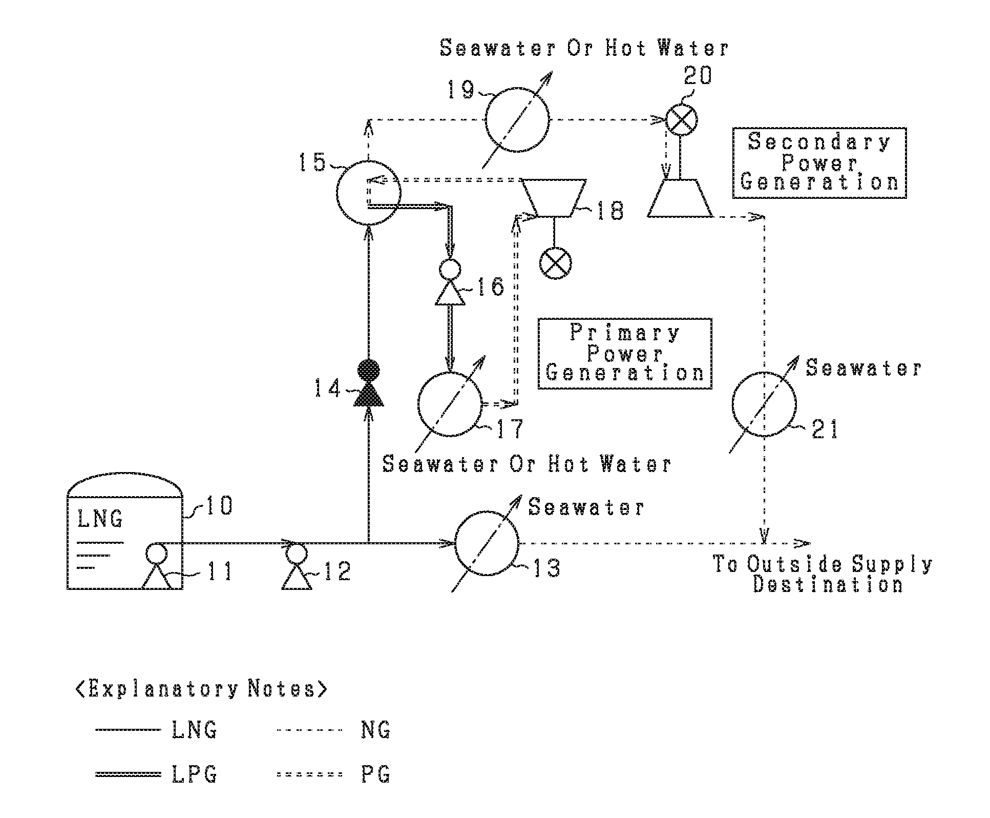
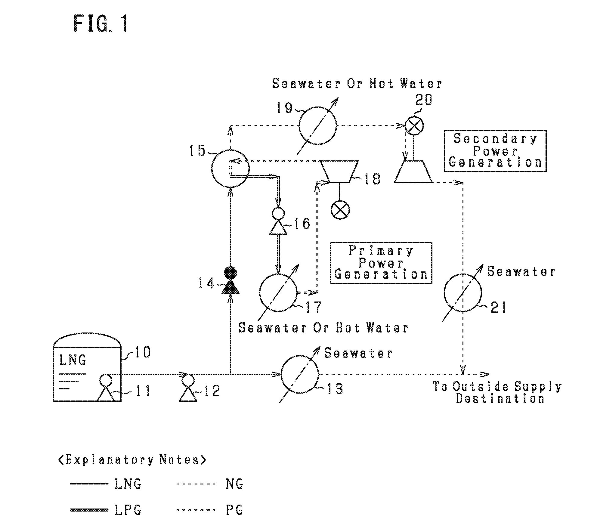
[0041]One embodiment in which the present invention is embodied as a cold energy power generation system will now be described with reference to the drawings. First, the overall configuration of a cold energy power generation system will be described with reference to FIG. 1. The cold energy power generation system generates electric power by utilizing the cold of liquefied natural gas (LNG) stored in a storage tank 10. In the present embodiment, there is shown an example in which the cold energy power generation system is applied to a vaporization apparatus that vaporizes the liquefied natural gas stored in the storage tank 10 and supplies it to the outside as a natural gas (NG).

[0042]As shown in FIG. 1, the liquefied natural gas stored in the storage tank 10 is increased in pressure by a primary pump 11 and is supplied to a secondary pump 12. The pressure of the supplied liquefied natural gas is increased further by the secondary pump 12. The liquefied natural gas whose pressure h...


PUM


Abstract

A cold energy power generation system increases the efficiency in utilizing the cold exergy of liquefied gas while freely controlling the gas supply pressure on the outlet side of a secondary expansion turbine. The system includes a pressure-increasing pump for increasing the pressure of a low-temperature liquefied gas to a pre-overboost pressure while maintaining the liquid gas in a liquid state, a Rankine-cycle-type primary power generation apparatus, a heater for heating a vaporized gas, and a direct-expansion-type secondary power generation apparatus. Since the cold exergy of the liquefied gas is more efficiently utilized as pressure exergy than as temperature exergy, the system converts the cold exergy more preferentially to pressure exergy, and the optimal operating conditions that maximize the conversion efficiency can be determined by the composition of the liquefied gas, the temperature of the heating source, and the gas supply pressure.

Description

CLAIM OF PRIORITY[0001]This application is a Continuation of International Patent Application No. PCT / JP2015 / 061508, filed on Apr. 14, 2015, which claims priority to Japanese Patent Application No. 2014-098091, filed on Apr. 19, 2014, each of which is hereby incorporated by reference.BACKGROUND OF THE INVENTION[0002]1. Field of the Invention[0003]The present invention relates to a cold utilization system which utilizes cold of a low-temperature liquefied gas stored in a storage tank, to an energy system including the cold utilization system, and to a method for utilizing the cold utilization system.[0004]2. Description of the Related Art[0005]An example of a known low-temperature liquefied gas is liquefied natural gas (LNG). Natural gas (NG) produced at a production site in a foreign country is cooled and liquefied through use of electric power, thereby producing liquefied natural gas. Liquefied natural gas having a reduced volume is imported by an LNG transport tanker. In general, ...

Claims


Application Information

Patent Timeline
Patent Type & Authority Applications(United States)
IPC IPC(8): F17C9/04F02C1/02F01K25/10
CPCF17C9/04F02C1/02F01K25/10F01K9/00F01K23/04Y02E20/16F17C7/04F17C2221/033F17C2223/0161F17C2225/0123F17C2225/035F17C2227/0135F17C2227/0178F17C2227/0316F17C2227/0318F17C2227/0393F17C2265/06F17C2265/07
Inventor TADA, MASASHI
Owner TADA MASASHI
Learn More