Millimetre-wave seat occupation radar sensor

a radar sensor and millimetre wave technology, applied in the direction of instruments, pedestrian/occupant safety arrangements, vehicular safety arrangements, etc., can solve the problems of increasing the system handling, difficult to integrate ultrasound hardware with electronics, and difficult to propose a system, etc., to achieve the effect of improving safety

Active Publication Date: 2017-02-09
NOVELIC D O O
View PDF5 Cites 25 Cited by
  • Summary
  • Abstract
  • Description
  • Claims
  • Application Information

AI Technical Summary

Benefits of technology

[0029]This invention proposed apparatus 100 and method of operation for seat oc

Problems solved by technology

The narrow antenna beam, associated with explicit high-gain antenna approach is essential part of the system, providing limited possibility that the biometric data, i.e. heartbeats or respirations, from the persons in the vicinity, but not on the seat.
On the other hand, integration of ultrasound hardware with electronics is quite difficult.Inherently compact size, which enables easy integration into a single compact low-cost module, presents a significant system advantage, hence almost eliminating practical use of the system proposed in U.S. Pat. No. 6,736,231.It would be very difficult for the system proposed in U.S. Pat. No. 6,736,231 to operate in the realistic scenario, with each of the seats monitored with a separate TX and a pair of RX parts.
Thus, they could work only if they are c

Method used


Image

  • Millimetre-wave seat occupation radar sensor
  • Millimetre-wave seat occupation radar sensor
  • Millimetre-wave seat occupation radar sensor

Examples


Embodiment Construction

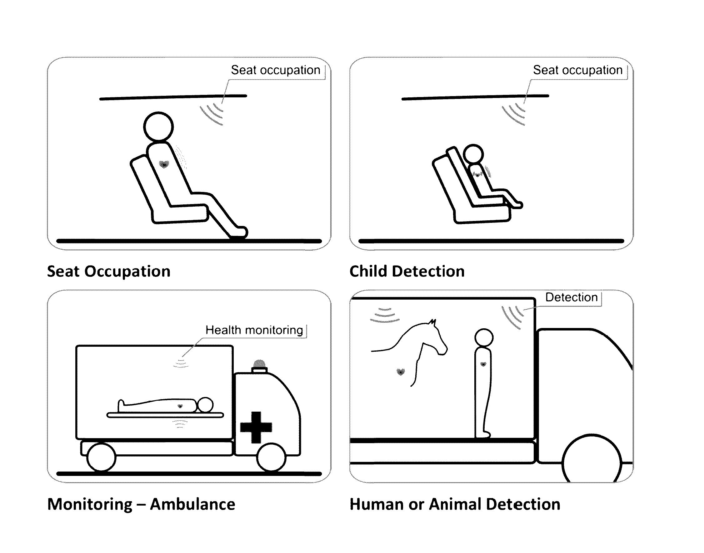
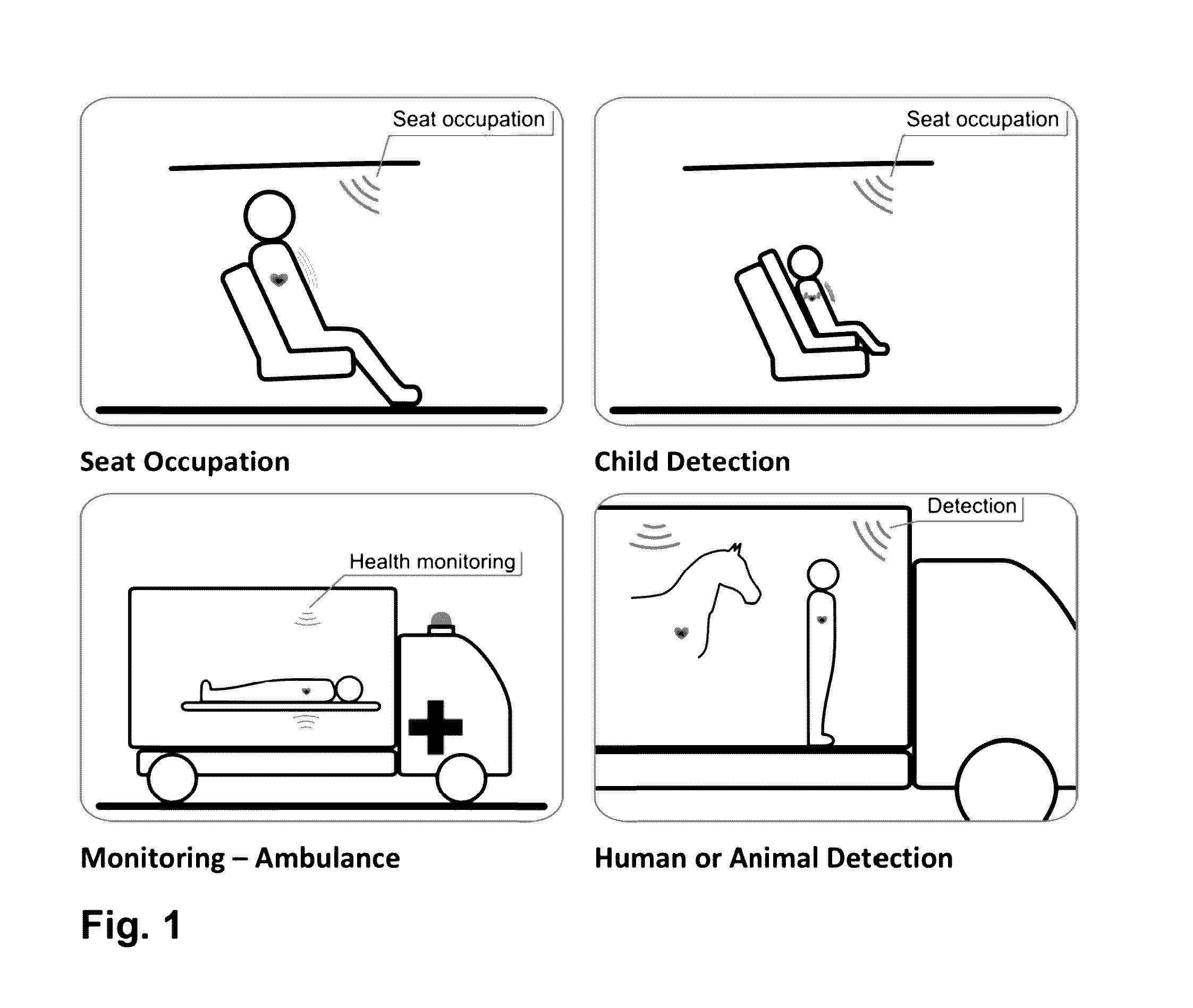
[0065]Apparatus 100 is preferably integrated in the vehicle, having Line-of-Sight (LOS), i.e. no obstacles, between the system and the human body, as shown in the FIG. 1. Some application scenarios are also illustrated in FIG. 1. Due to advantageously proposed mm-wave radar application, the size of the high-gain Antenna System for RX 21 and for TX 22 is small enough to allow practical use of the apparatus in the vehicle cabin while maintaining high-gain antenna features. Taking into account proposed 60 GHz ISM band operation, or alternatively 77-79 GHz operation, and 4×4 antenna elements for 21 and 22, the approximate size of the device may be less than 4×2×1 cm, which would inherently allow practical use in vehicle cabins.

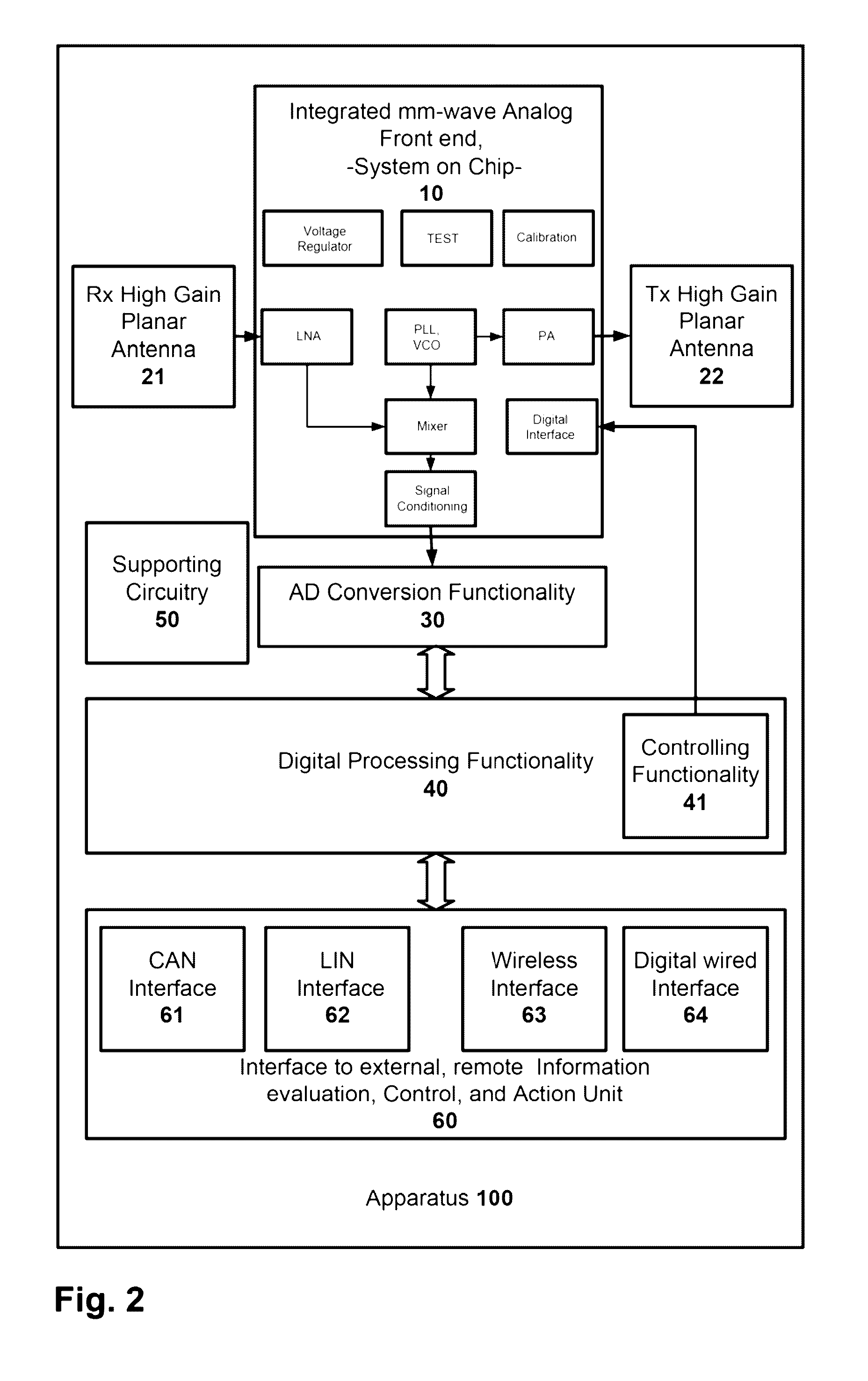
[0066]The crucial block of the proposed apparatus 100 is the Integrated mm-wave front end, -System on Chip- 10. It contains the complete RF functionality, and includes power amplifier functionality attached to the antenna system 22, low noise amplifier attached to...


PUM


Abstract

The present invention discloses a mm-wave radar sensor to be deployed in the vehicles for seat occupation detection applications. The key system relevant components are utilization of mm-wave integrated radar, specific planar high-gain antenna radiation pattern, and analyzing of the heartbeat and optionally also respiratory dynamics. The method of operation calculates probability of the seat occupation event regarding: detection of the passenger on the seat, detection of a baby or a child on the seat, detection of the presence of a baby or a child in the vehicle after the driver has left the vehicle, detection of the human or animal presence of intrusion in specific vehicle environment. In case that probability is above a predefined threshold, typically the interaction with vehicle control system is initiated using arbitrary automotive interfaces. Corresponding predefined actions are taken in that case. The predefined actions could be one or combination of the following: audio signal alerts to driver, inside cabin light condition change, engine operation condition change, opening of the windows or corresponding communication using arbitrary wireless means to outside vehicle environment. Optionally, the system is utilizing additional parameters like vehicle cabin temperature and/or timing information about engine stop and driver leaving the car. Preferably, the system is using 60 GHz or 77-79 GHz integrated radar front end working in Doppler operation mode, with 4×4 Tx and Rx planar radiation elements, with physical size typically in the range 4×2×1 cm, or smaller.

Description

TECHNICAL FIELD[0001]The present invention relates to a seat occupation sensor and decision making device comprising mm-wave radar with planar high-gain antenna systems, utilizing information extracted from processing of both human heartbeat and breathing dynamics.BACKGROUND ART[0002]There is a strong motivation to deploy the smart seat occupation sensor in the following applications:[0003]a) Detection of a human being on a seat.[0004]b) Differentiation of the human being on the seat from the weight, potentially replacing seat pressure sensor commonly used in vehicles today.[0005]c) Differentiation of the baby or child on a seat from the weight or adult.[0006]d) Minimizing the loss olives of babies or disabled persons left in a car on the sun.[0007]e) Detection of the humans or animals in the vehicle areas.[0008]f) Aftermarket seat occupation detection integration, i.e. deployment of the innovative apparatus in the vehicle cabin after the manufacturing of the vehicle is finished, wh...

Claims


Application Information

Patent Timeline
IPC IPC(8): G08B21/06H01Q1/22H01Q9/28B60N2/00H01Q1/32
CPCG08B21/06B60N2/002H01Q1/2283H01Q9/285H01Q1/3291B60R21/01534
Inventor BRANKOVIC, VESELINGRUJIC, DUSANJOVANOVIC, PAVLEMIHAJLOVIC, VELJKOSAVIC, MILANTASOVAC, DARKO
Owner NOVELIC D O O
Why Eureka
Try Eureka