
Modular Unit Comprising A Laminate Stack For An Electric Machine, Method For Producing Such A Modular Unit, And Electric Machine

Active Publication Date: 2017-02-09
ZF FRIEDRICHSHAFEN AG
View PDF18 Cites 2 Cited by
  • Summary
  • Abstract
  • Description
  • Claims
  • Application Information

AI Technical Summary

Benefits of technology

The present invention is for a component unit for an electric machine. It is designed to prevent the lamination stack from fanning out and to securely fix it to its carrier element. This is achieved through a process called staking, which involves plastically displacing material and creating a secure connection. The staking region can be constructed in a single step or multiple steps, and it allows for increased pressure and a higher area density in the connection. Overall, this invention ensures a reliable and secure connection between the lamination stack and its carrier element.

Problems solved by technology

This adversely affects the efficiency of an electric machine of this type.

Method used


Image

  • Modular Unit Comprising A Laminate Stack For An Electric Machine, Method For Producing Such A Modular Unit, And Electric Machine
  • Modular Unit Comprising A Laminate Stack For An Electric Machine, Method For Producing Such A Modular Unit, And Electric Machine
  • Modular Unit Comprising A Laminate Stack For An Electric Machine, Method For Producing Such A Modular Unit, And Electric Machine

Examples


Embodiment Construction

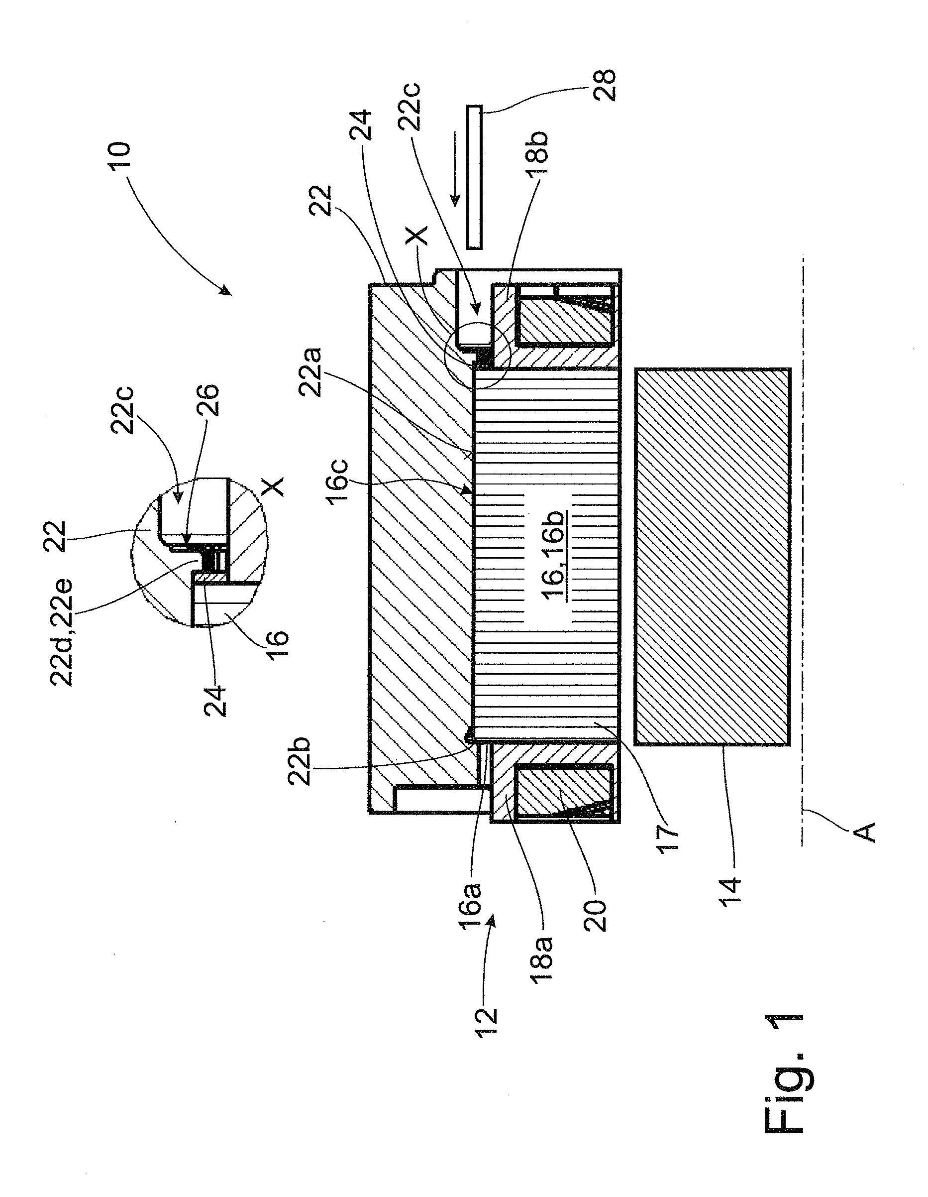
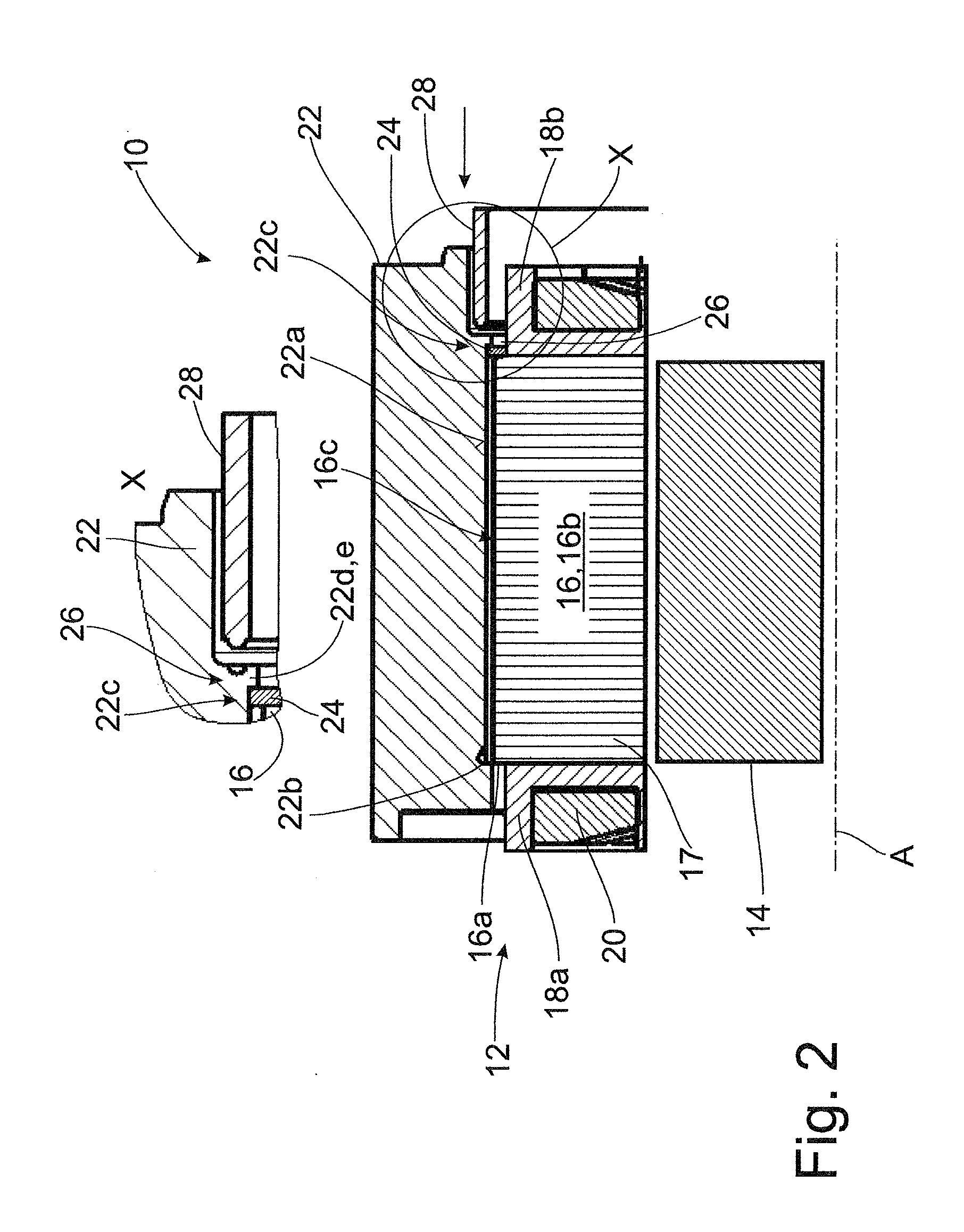
[0039]Like objects, functional units or comparable components are denoted by identical reference numerals throughout the different drawings. Further, collective reference numerals may be used for components and objects which occur more than once in an embodiment example or diagram but which are described collectively with respect to one or more features. Components or objects which are denoted by identical reference numerals or collective reference numerals may be constructed identically or possibly also differently with respect to one or more or all features, for example, their dimensions, unless otherwise explicit or implicit from the description.

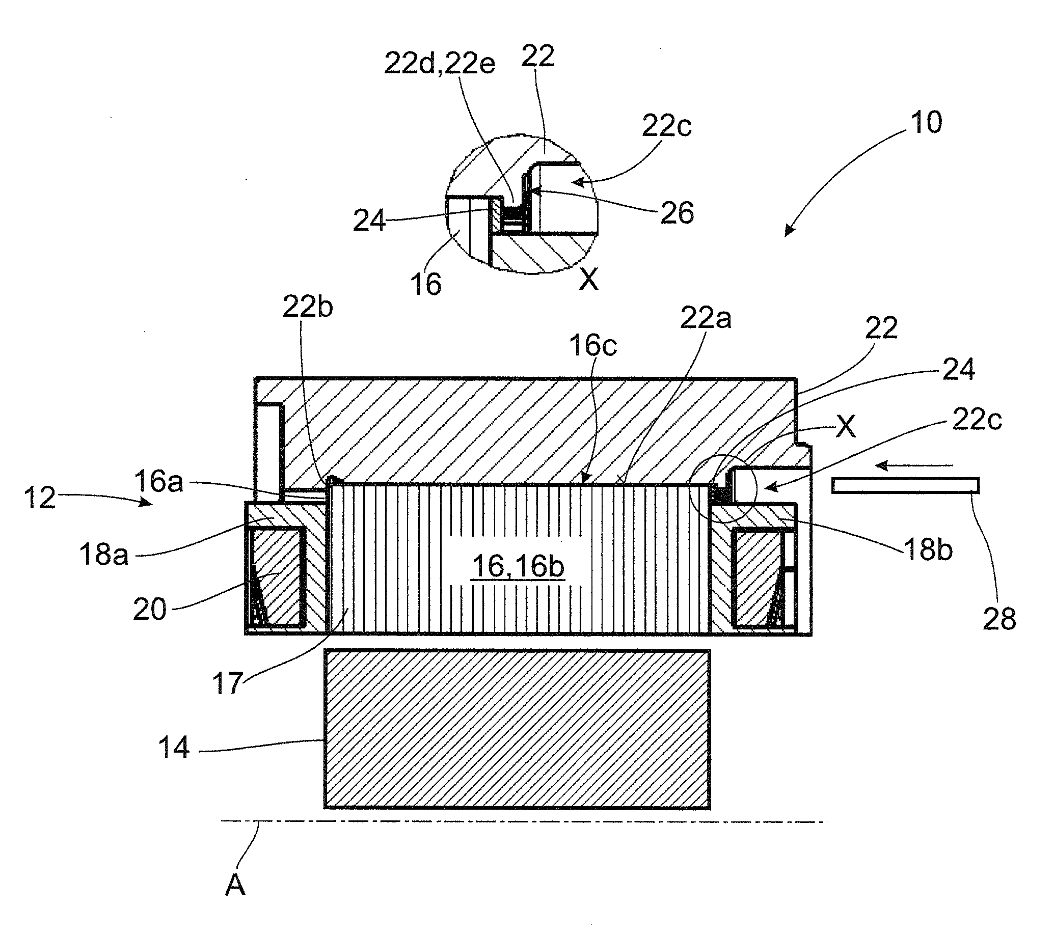
[0040]The drawings show an electric machine 10 with a stator 12 and a rotor 14 which is supported so as to be rotatable relative to the stator 12 around an axis A. The stator 12 or stator component unit 12 will be described more fully by way of example in the following. This component unit 12 comprises an annular lamination stack 16 made ...


PUM


Abstract

A component unit for an electric machine includes an annular lamination stack formed of a plurality of axially stacked laminations. The lamination stack is secured by an inner or outer cylindrical fastening portion to a cylindrical receiving portion of a carrier element. The carrier element has two stops between which the lamination stack is axially clamped in a frictionally engaging manner. At least one of the axial stops has an annular supporting element arranged at the receiving portion and supports the lamination stack and which is fixed at the carrier element by at least one staking region.

Description

CROSS REFERENCE TO RELATED APPLICATIONS[0001]This is a U.S. national stage of application No. PCT / EP2015 / 055124, filed on Mar. 12, 2015. Priority is claimed on German Application No. DE102014206848.7, filed Apr. 9, 2014, the content of which is incorporated here by reference.BACKGROUND OF THE INVENTION[0002]1. Field of the Invention[0003]The present invention is directed to a component unit with a lamination stack for an electric machine, a method for the production of a component unit of this type, and to an electric machine having a component unit of this type.[0004]2. Description of the Prior Art[0005]The electromagnetic components of electric machines frequently comprise lamination stacks of magnetizable electrical steel. To prevent eddy current losses, lamination stacks of this type are built from a plurality of axially staggered laminations that are connected to one another, for example, either with a thermosetting varnish or through in-die stacking lugs engaging one inside th...

Claims


Application Information

Patent Timeline
IPC IPC(8): H02K1/18
CPCH02K1/185H02K1/187H02K15/14H02K2201/09
Inventor BYZIO, BERNARDWOLF, WALTERWEHNER, ERHARD
Owner ZF FRIEDRICHSHAFEN AG
Learn More