
Dynamic voltage level shifters employing pulse generation circuits, and related systems and methods

a voltage level shifter and pulse generation technology, applied in logic circuits, logic functions, pulse techniques, etc., can solve problems such as error-prone output signals, and achieve the effect of reducing drive strength and less competition

Inactive Publication Date: 2017-02-16
QUALCOMM INC
View PDF1 Cites 6 Cited by
  • Summary
  • Abstract
  • Description
  • Claims
  • Application Information

AI Technical Summary

Benefits of technology

The patent describes a circuit that generates a pulse signal based on the difference in supply voltages of two groups of components. The pulse width (the duration of the pulse) is determined by this difference. A "keeper circuit" is also included to control the strength of the pulse for a certain duration of time. This results in the ability to drive a dynamic node to the ground voltage while reducing the competition from the keeper circuit, even as the difference in supply voltages increases. Technical effects include improved control over grounding and reduced interference between components, leading to improved performance and reliability of the circuit.

Problems solved by technology

For example, as the difference in supply voltages in the higher and lower voltage domains increases, an input signal in the lower voltage domain may concurrently partially activate an evaluate circuit and a keeper circuit in a dynamic voltage level shifter, potentially leading to erroneous output signals.

Method used


Image

  • Dynamic voltage level shifters employing pulse generation circuits, and related systems and methods
  • Dynamic voltage level shifters employing pulse generation circuits, and related systems and methods
  • Dynamic voltage level shifters employing pulse generation circuits, and related systems and methods

Examples


Embodiment Construction

[0020]With reference now to the drawing figures, several exemplary aspects of the present disclosure are described. The word “exemplary” is used herein to mean “serving as an example, instance, or illustration.” Any aspect described herein as “exemplary” is not necessarily to be construed as preferred or advantageous over other aspects.

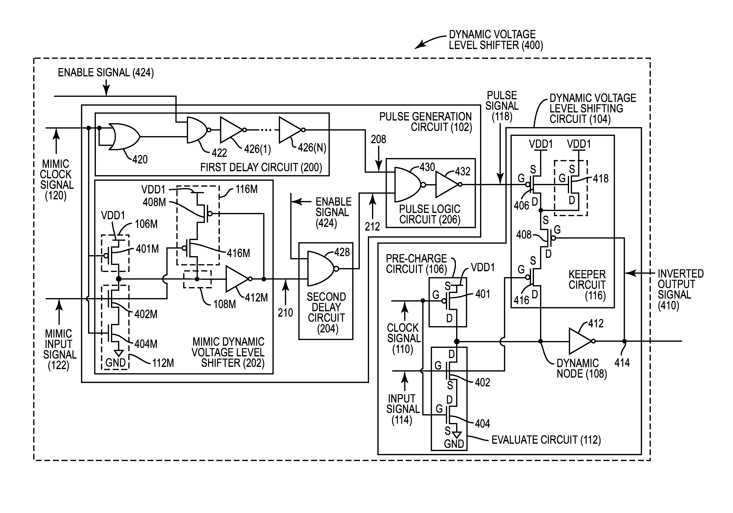
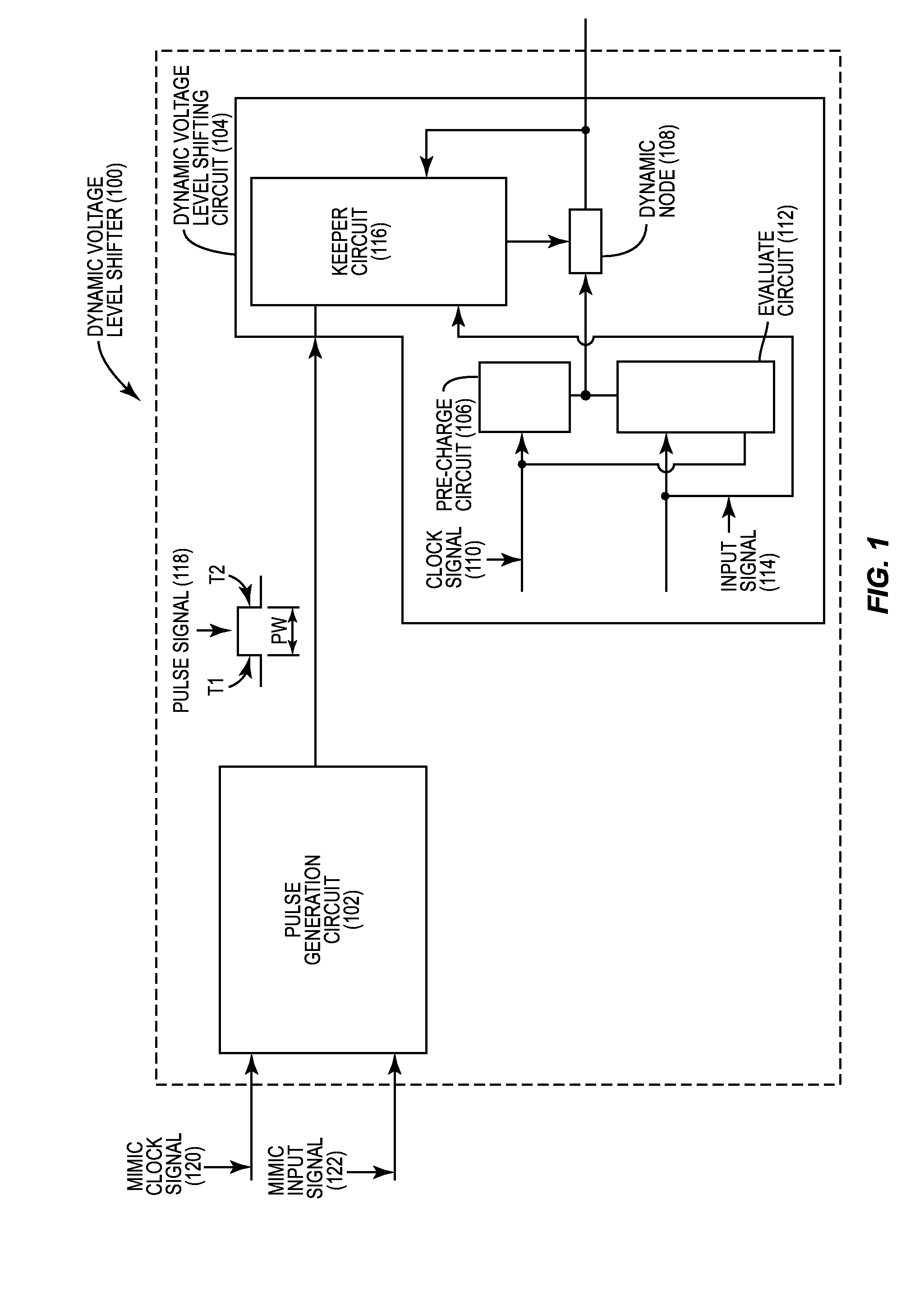
[0021]FIG. 1 illustrates an exemplary dynamic voltage level shifter 100 employing a pulse generation circuit 102 and a dynamic voltage level shifting circuit 104. The dynamic voltage level shifting circuit 104 includes a pre-charge circuit 106 that is configured to provide a supply voltage of a first voltage domain to a dynamic node 108 in response to a clock signal 110 in the first voltage domain having a pre-charge voltage (e.g., a logic low ‘0’ voltage). The dynamic voltage level shifting circuit 104 also includes an evaluate circuit 112 that is configured to provide a ground voltage to the dynamic node 108 in response to an input signal 114 in a s...


PUM


Abstract

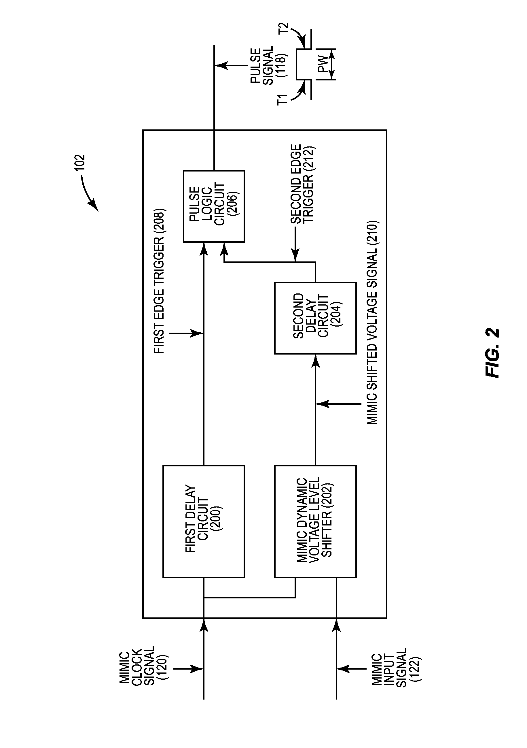
Dynamic voltage level shifters employing pulse generation circuits are disclosed. In one aspect, a dynamic voltage level shifter includes a dynamic voltage level shifting circuit. The dynamic voltage level shifting circuit includes a pre-charge circuit configured to provide supply voltage of a first voltage domain to a dynamic node in response to a clock signal having pre-charge voltage. An evaluate circuit is configured to provide ground voltage to the dynamic node in response to an input signal having an active voltage while the clock signal has evaluate voltage. A keeper circuit is configured to provide a reduced drive strength to the dynamic node in response to pulse signal. The pulse signal is generated by a pulse generation circuit, wherein a pulse width of the pulse signal correlates to a difference in supply voltages of first and second voltage domains.

Description

BACKGROUND[0001]I. Field of the Disclosure[0002]The technology of the disclosure relates generally to voltage level shifters for shifting input signals in one voltage domain to output signals in another voltage domain, and particularly to reducing area of voltage level shifters.[0003]II. Background[0004]Processor-based systems may be powered by one or more power supplies, wherein such power supplies provide voltage for processor operations. Particular components within a processor-based system may use less voltage to operate as compared to other components within the same system. For example, a processor in a processor-based system may use less voltage to operate during idle modes, but memory may use a higher minimum voltage to retain data. In this regard, rather than providing a single higher voltage supply to all components in a processor-based system, components of the processor-based system can be configured to operate in multiple voltage domains. Components that operate at a lo...

Claims


Application Information

Patent Timeline
Patent Type & Authority Applications(United States)
IPC IPC(8): H03K19/0185H03K19/20
CPCH03K19/20H03K19/018528H03K3/356121H03K19/0963
Inventor CHAI, CHIAMINGGE, SHAOPINGLILES, STEPHEN EDWARDSHAH, CHINTAN HEMENDRAKUMAR
Owner QUALCOMM INC
Learn More