High-current electrical circuit having a circuit board and a busbar

Active Publication Date: 2017-02-16
ELLENBERGER POENSGEN
View PDF8 Cites 0 Cited by
  • Summary
  • Abstract
  • Description
  • Claims
  • Application Information

AI Technical Summary

Benefits of technology

The invention aims to provide an electrical circuit that is cheap to make and can be adapted to various needs.

Problems solved by technology

The cost of producing circuit boards of this kind is relatively high.

Method used


Image

  • High-current electrical circuit having a circuit board and a busbar
  • High-current electrical circuit having a circuit board and a busbar
  • High-current electrical circuit having a circuit board and a busbar

Examples


Embodiment Construction

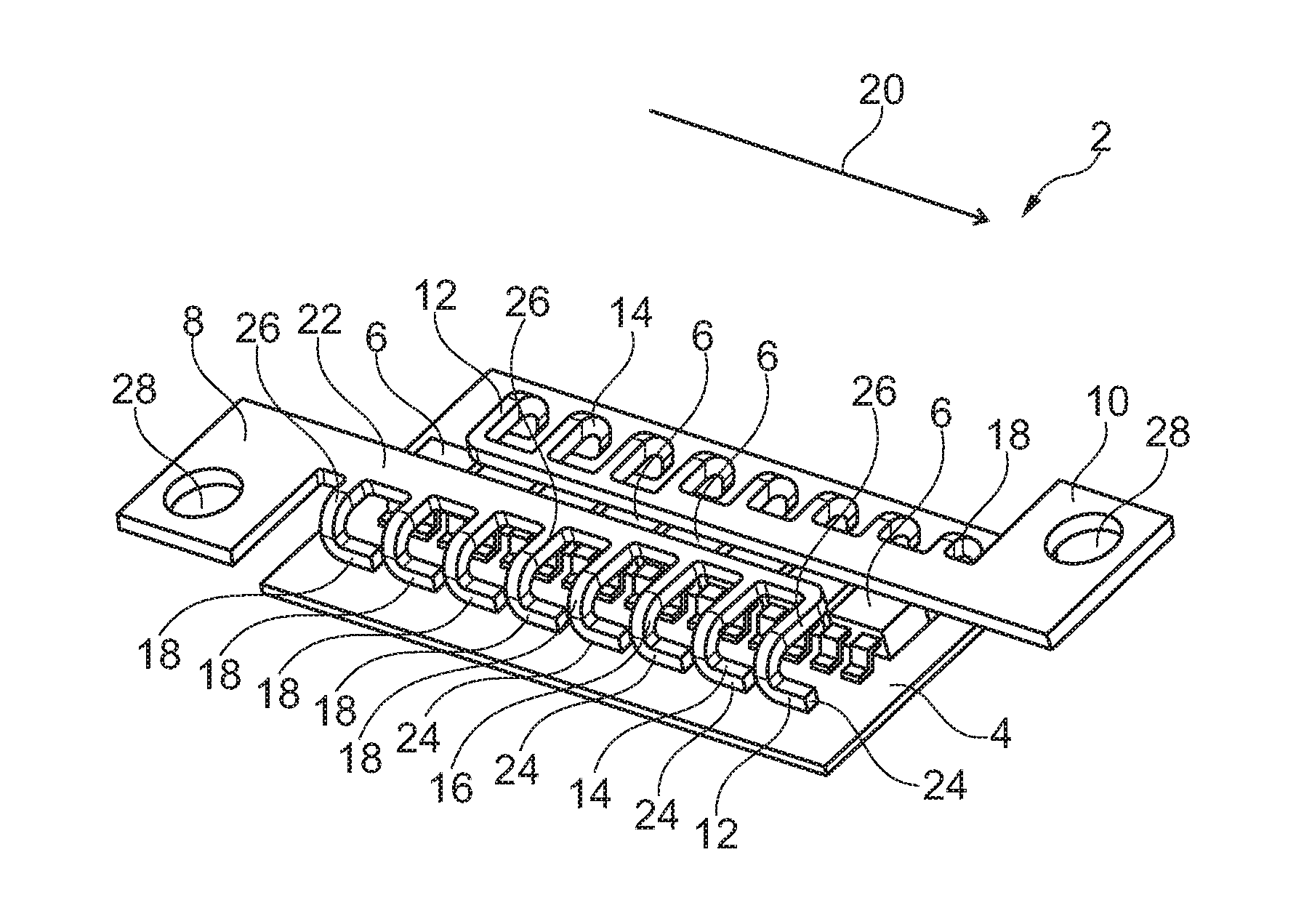
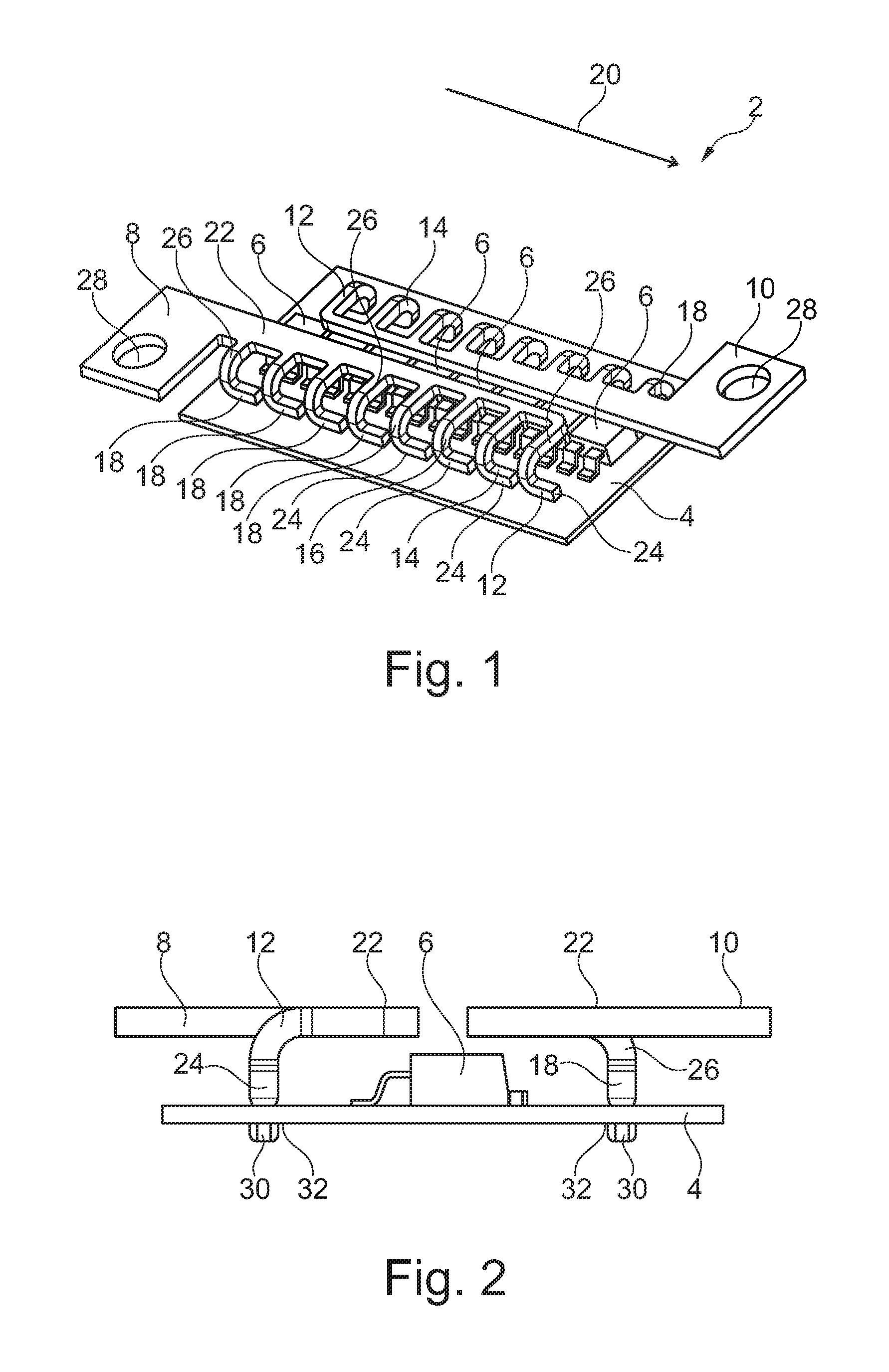
[0037]An electrical circuit 2 with a plate-shaped circuit board 4 is shown perspectively in FIG. 1. Circuit board 4 comprises a plate made of a fiber-reinforced plastic, for example, fiberglass cloth, which is impregnated with epoxy resin. A copper layer, which is partially removed to create traces (not shown), is applied to the plastic plate. In other words, circuit board 4 has a printed circuit. Electrical circuit 2 comprises further electrical components 6, of which eight transistors in the form of MOSFETs are shown. Electrical circuit 2 further has a first busbar 8 and a second busbar 10, which have the same structure and are fastened to circuit board 4. In this case, second busbar 10 is positioned rotated by 180° in comparison with first busbar 8. Each busbar 8, 10 has a first connection 12, a second connection 14, a third connection 16, and five further connections 18, whose cross section is the same, and which are connected to substantially L-shaped supporting body 22 extendi...


PUM


Abstract

An electrical circuit including a circuit board on which a number of electrical and / or electronic components are mounted, and a busbar that has a supporting body and a first, second, and third connection. The supporting body is spaced apart from the circuit board and the connections are brought into electrical contact both with the supporting body and with the circuit board. The supporting body has a first cross section between the first and second connection and a second cross section between the second and third connection, wherein the first cross section is smaller than the second cross section. The invention further relates to a bus bar.

Description

[0001]This nonprovisional application is a continuation of International Application No. PCT / EP2015 / 059280, which was filed on Apr. 29, 2015, and which claims priority to German Patent Application No. 10 2014 006 360.7, which was filed in Germany on Apr. 30, 2014, and which are both herein incorporated by reference.BACKGROUND OF THE INVENTION[0002]Field of the Invention[0003]The invention relates to an electrical circuit comprising a circuit board on which a plurality of electrical and / or electronic components are mounted.[0004]Description of the Background Art[0005]Commercial vehicles, e.g., refrigerated trucks, have electrically operated auxiliary units such as in particular a refrigeration system or hoists. Switching of the current circuit supplying the particular unit is necessary for operation, and usually occurs by means of power semiconductor switches. The on-board system of commercial vehicles has an electrical voltage of 24 V. In order to supply relatively high-power auxili...

Claims


Application Information

Patent Timeline
IPC IPC(8): H05K1/18H01B5/02H05K1/02
CPCH05K1/18H05K1/0213H05K2201/10409H05K2201/10272H01B5/02H01R12/7088H01R25/161H05K1/0263H05K7/1432H01R12/58H01R4/34H01R11/12H01R12/53H01R12/585H01R2201/26H03K17/95H03K17/9545H03K2017/9527H05K3/32H05K7/14329
Inventor ULLERMANN, WOLFGANGENGEWALD, MANUELMIKLIS, MARKUS
Owner ELLENBERGER POENSGEN
Why Eureka
Try Eureka