
Semiconductor package with pillar-top-interconnection (PTI) configuration and its mis fabricating method

a technology of pillar-top interconnection and semiconductor devices, which is applied in the direction of semiconductor devices, semiconductor/solid-state device details, electrical apparatus, etc., can solve the problems of difficult fabrication of tmvs b>311/b>, and cannot be shaped, so as to shrink the layout pitch and the effect of small footprin

Active Publication Date: 2017-02-23
POWERTECH TECHNOLOGY
View PDF0 Cites 30 Cited by
  • Summary
  • Abstract
  • Description
  • Claims
  • Application Information

AI Technical Summary

Benefits of technology

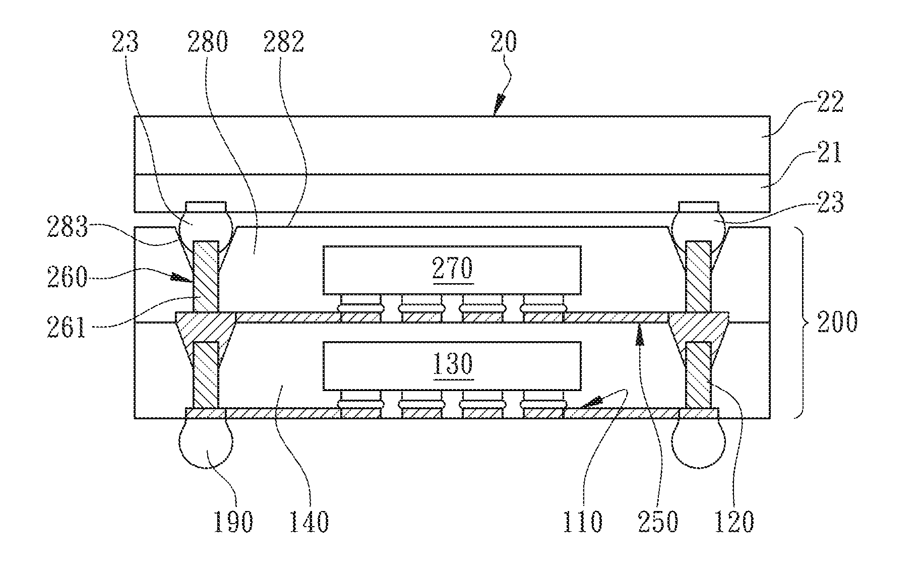
The present invention provides a semiconductor package with Pillar-Top-Interconnection (PTI) configuration and its manufacturing method by Molded-Interconnect-Substrate (MIS) process. This method allows for the elimination of conventional molding thickness on IC substrate and conventional POP stacking gap between the stacked packages, resulting in a smaller and thinner semiconductor package. The method also allows for the achievement of a zero gap between the PTO stacked assembly and eliminates package thickness on the substrate.

Problems solved by technology

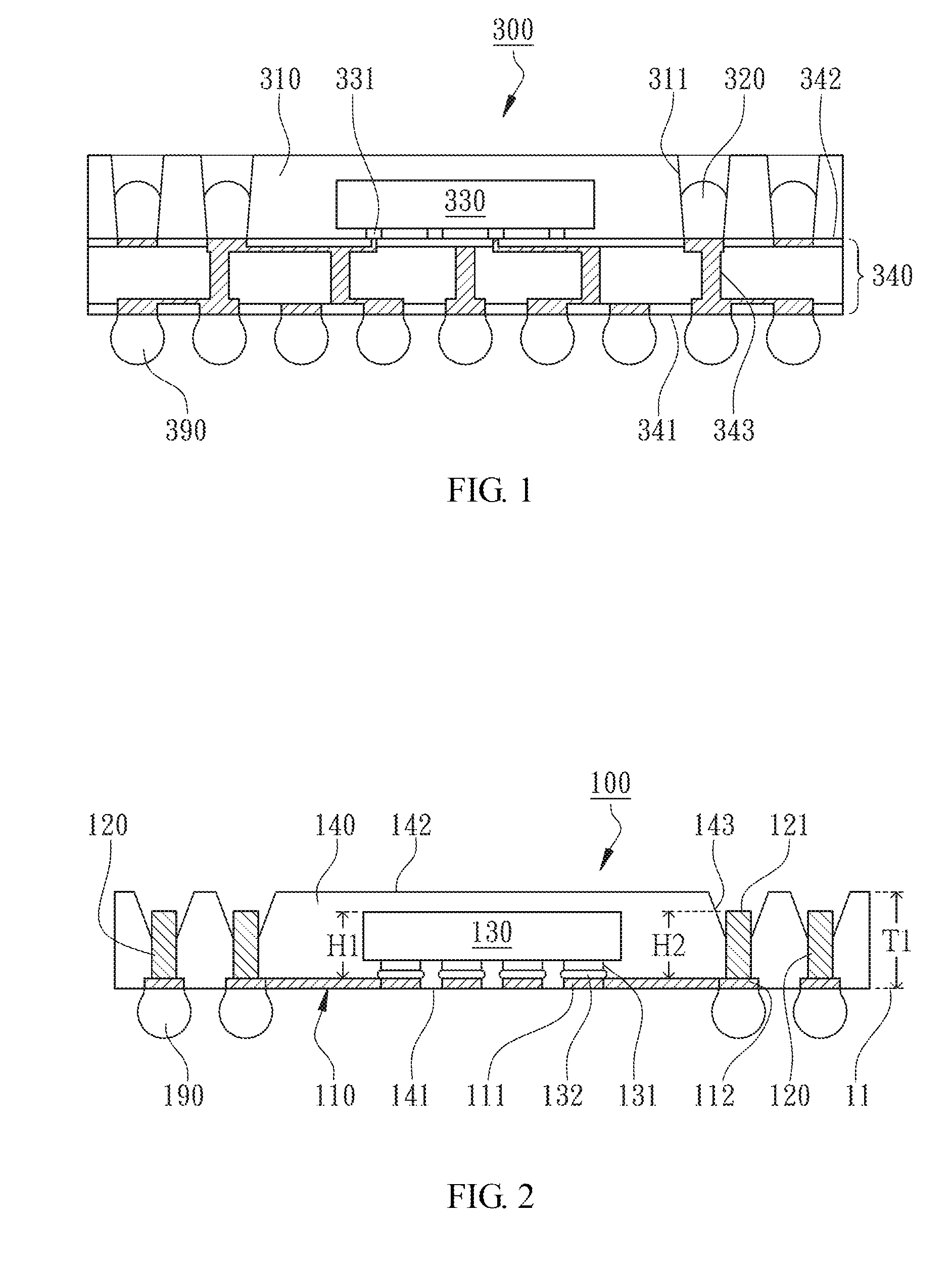
Even reflowing, the filled solder pastes 320 can not be shaped as solder balls under the limitation of the TMVs 311, but the fabrication of the TMVs 311 is difficult.

Method used


Image

  • Semiconductor package with pillar-top-interconnection (PTI) configuration and its mis fabricating method
  • Semiconductor package with pillar-top-interconnection (PTI) configuration and its mis fabricating method
  • Semiconductor package with pillar-top-interconnection (PTI) configuration and its mis fabricating method

Examples


Embodiment Construction

[0013]With reference to the attached drawings, the present invention is described by means of the embodiment(s) below where the attached drawings are simplified for illustration purposes only to illustrate the structures or methods of the present invention by describing the relationships between the components and assembly in the present invention. Therefore, the components shown in the figures are not expressed with the actual numbers, actual shapes, actual dimensions, nor with the actual ratio. Some of the dimensions or dimension ratios have been enlarged or simplified to provide a better illustration. The actual numbers, actual shapes, or actual dimension ratios can be selectively designed and disposed and the detail component layouts may be more complicated.

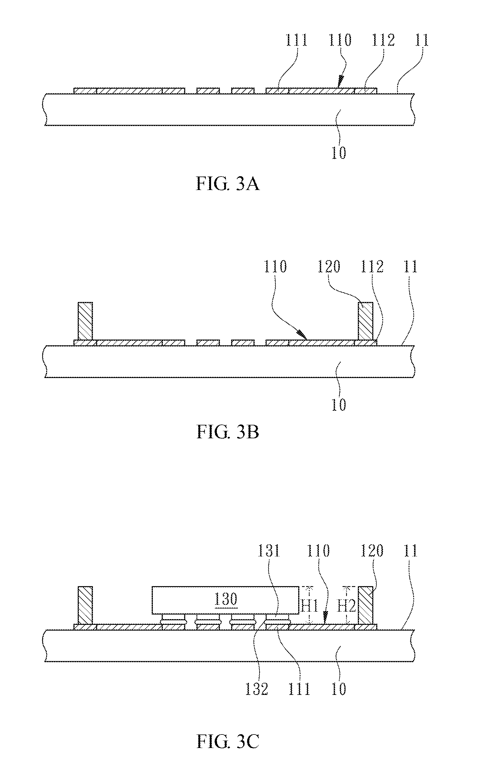
[0014]According to the first embodiment of the present invention, a semiconductor package 100 is illustrated in FIG. 2 for a cross-sectional view and from FIGS. 3A to 3E for cross-sectional views illustrating components manuf...


PUM


Abstract

Disclosed is a semiconductor package with Pillar-Top-Interconnection (PTI) configuration, comprising a redistribution layer (RDL) formed on a carrier plane, a plurality of metal pillars disposed on the RDL, a chip bonded onto the RDL, and a molding core. The molding core is formed on the carrier plane and has a bottom surface defined by the carrier plane so that the RDL is embedded inside the molding core. The package thickness of the molding core is greater than the chip-bonding height of the chip so that the chip is completely embedded inside the molding core. The metal pillars are encapsulated at the peripheries of the molding core with a plurality of pillar top portions exposed from the molding core. The exposed pillar top portions are reentrant from a top surface of the molding core and uneven. Accordingly, it realizes the effects of ultra-thin and smaller footprint POP stacked assembly with fine pitch vertically electrical connections in POP structure. Also, it is possible to achieve zero spacing between POP stacked assembly.

Description

FIELD OF THE INVENTION[0001]The present invention relates to a semiconductor package and more specifically to a semiconductor package with Pillar-Top-Interconnection (PTI) configuration to be implemented in POP stacked assembly and a method for the manufacturing the same by utilizing Molded-Interconnect-Substrate (MIS) process.BACKGROUND OF THE INVENTION[0002]POP (Package-On-Package) is formed by vertically stacking a plurality of semiconductor packages to manufacture a 3D stacked assembly where the top semiconductor package is mounted on the bottom semiconductor package by SMT (Surface Mounting). The vertically electrical interconnection between the stacked packages is connected by a plurality of upper solder balls of the top semiconductor package with ball-on-ball interconnection where a POP stacking gap is inevitable. Moreover, an encapsulant of the bottom semiconductor package is formed on a chip carrier substrate where a molding height is added and the peripheries of the encaps...

Claims


Application Information

Patent Timeline
IPC IPC(8): H01L25/065H01L23/48H01L23/498H01L21/48H01L21/56H01L21/683H01L25/00H01L23/00H01L23/31
CPCH01L25/0657H01L2224/81191H01L23/481H01L23/49838H01L23/3128H01L21/565H01L21/6835H01L21/568H01L25/50H01L24/81H01L21/4853H01L2225/06513H01L2225/06517H01L2225/06548H01L2224/16145H01L2224/16227H01L2924/15321H01L2924/1511H01L2221/68345H01L2221/68359H01L24/17H01L25/105H01L2225/06524H01L23/3107H01L2224/16245H01L2224/81005H01L2225/1023H01L2225/1029H01L2924/15192H01L2924/15311H01L2924/15331H01L2924/1815
Inventor YEH, YUN-HSINHSU, HUNG-HSIN
Owner POWERTECH TECHNOLOGY
Learn More