
Light guide device and virtual image display apparatus

a technology of virtual image display and guide device, which is applied in the direction of optical light guides, instruments, optics, etc., can solve the problems of peak wavelength selectivity (diffraction efficiency with respect, not necessarily easy to enlarge the pupil size), and achieve the effect of suppressing color unevenness

Active Publication Date: 2017-03-02
SEIKO EPSON CORP
View PDF3 Cites 14 Cited by
  • Summary
  • Abstract
  • Description
  • Claims
  • Application Information

AI Technical Summary

Benefits of technology

The light guide device described in this patent text uses a diffraction optical element to enlarge the pupil size and reduce color unevenness, resulting in a brighter display. This is possible because the diffraction optical element is only effective in the second directions, while in the first directions, streaks of unevenness can be easily avoided. The size of the pupil increases in the first directions with the thickness of the optical element that contributes to the virtual image formation, but the size can be kept smaller by not using the diffraction optical element in the first directions. This allows the device to be made thinner and smaller. In summary, this technology improves image quality and provides a better viewing experience for users.

Problems solved by technology

However, the diffraction gratings, i.e., the diffraction devices are used, and the peak of wavelength selectivity (diffraction efficiency with respect to wavelength) shifts depending on the angle of view of image light and color unevenness depending on the position within the screen is caused.
Further, regarding the first directions, the diffraction optical element is not used and the enlargement of the pupil size is not necessarily easy, however, regarding the second directions, the pupil size may be reliably enlarged by the diffraction optical element.

Method used


Image

  • Light guide device and virtual image display apparatus
  • Light guide device and virtual image display apparatus
  • Light guide device and virtual image display apparatus

Examples


first embodiment

[0035]As below, a virtual image display apparatus with a light guide device according to the first embodiment of the invention incorporated therein will be explained.

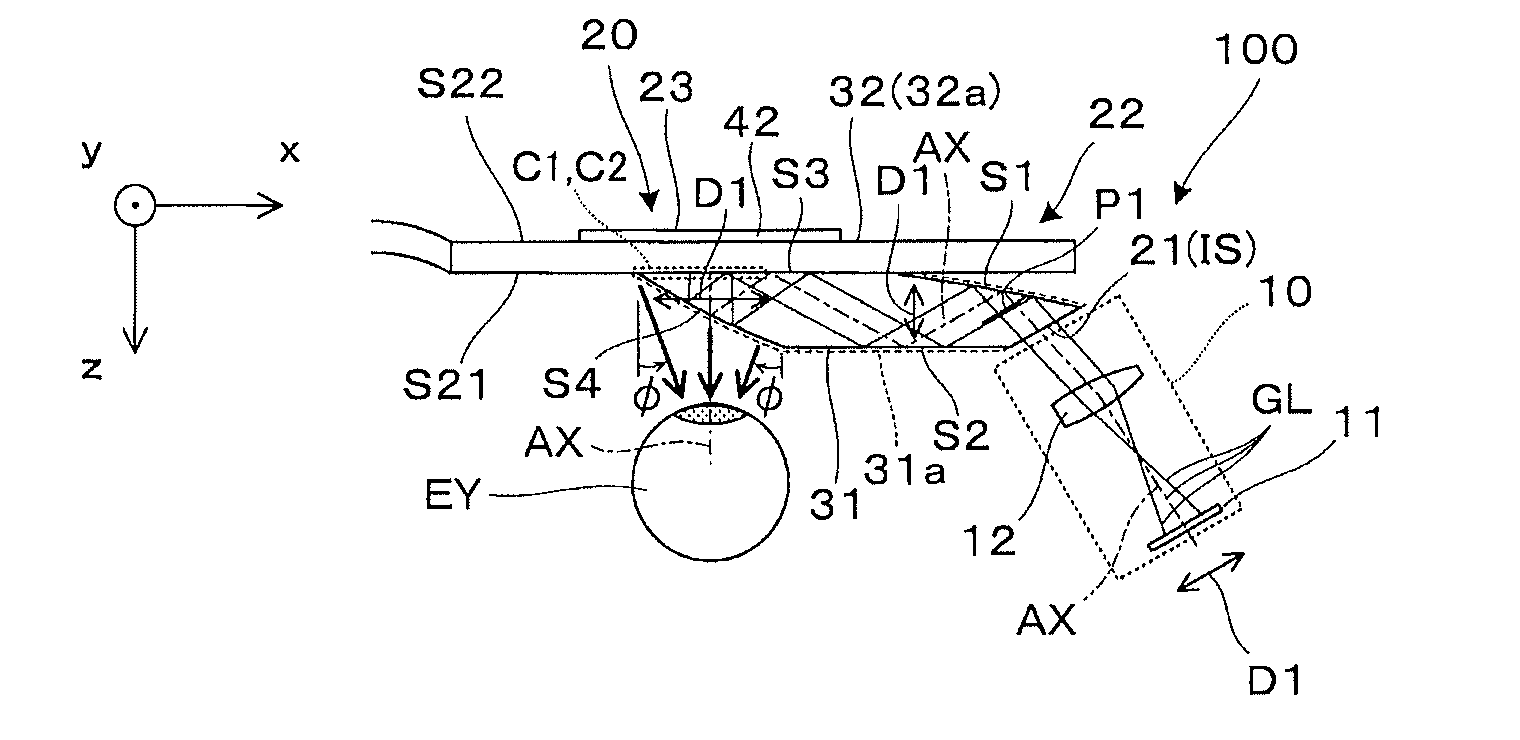
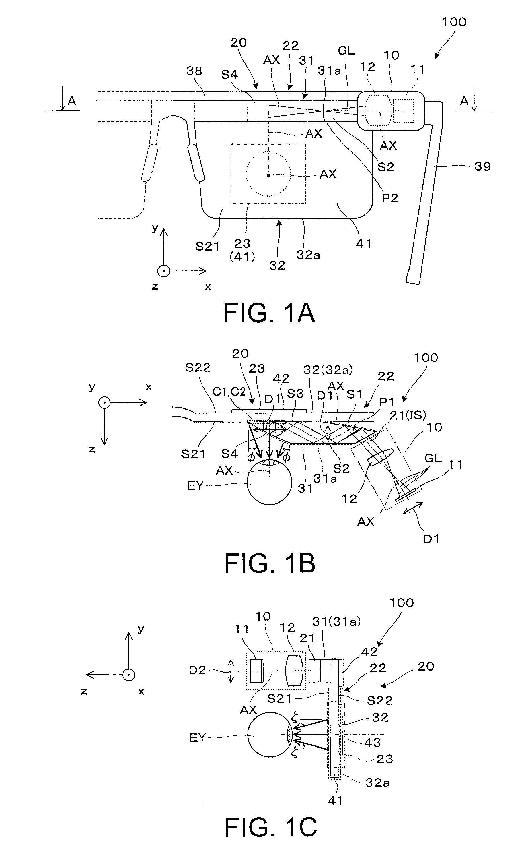
[0036]A virtual image display apparatus 100 shown in FIGS. 1A to 1C is applied to a head mounted display and includes an image forming device 10 and a light guide device 20 as a pair. Note that FIG. 1B corresponds to a section along A-A of the virtual image display apparatus 100 shown in FIG. 1A.

[0037]The virtual image display apparatus 100 allows an observer to recognize a color picture as a virtual image and observe an outside world image in see-through vision. In the virtual image display apparatus 100, the pair of the image forming device 10 and the light guide device 20 are generally provided for each of the right eye and the left eye of the observer, and the devices for right eye and left eye are symmetric and only the devices for right eye are shown here and the illustration of the devices for left eye are omitte...

second embodiment

[0071]As below, a virtual image display apparatus with a light guide device according to the second embodiment of the invention incorporated therein will be explained. Note that the light guide device according to the second embodiment is obtained by partially changing the light guide device according to the first embodiment and the explanation of the parts in common will be omitted.

[0072]As shown in FIG. 9, the light guide device 20 of the embodiment uses not reflective, but transmissive volume holograms as the first hologram element 42 and the second hologram element 43. In this case, the first hologram element 42 is provided between the first light guide member 31 and the light guide plate 41. The first hologram element 42 changes the traveling directions of the picture lights GL passing through the element to traveling directions at angles at which the lights are propagated while being totally reflected within the light guide plate 41. The second hologram element 43 is attached ...

third embodiment

[0073]As below, a virtual image display apparatus with a light guide device according to the third embodiment of the invention incorporated therein will be explained. Note that the light guide device according to the third embodiment is obtained by partially changing the light guide device according to the first embodiment and the explanation of the parts in common will be omitted.

[0074]As shown in FIG. 10, in the light guide device 20 of the embodiment, the first light guide member 31 is provided outside on the opposite side to the eye EY with the second light guide member 32 in between. By the arrangement, the first light guide member 31 on the light-incident side and the image forming device 10 do not interfere with the face, and the optical design becomes easier.

[0075]In the case of the embodiment, the first hologram element 42 is of reflective type and provided on the eye EY side of the light guide plate 41, and the second hologram element 43 is of reflective type and provided ...


PUM


Abstract

A light guide device may be incorporated into a virtual image display apparatus, and functionally includes a light-incident part for entrance of picture lights, a light guide part that guides the picture lights via the light-incident part, and a light-exiting part that outputs the picture lights from the light guide part to a position of an eye. In the light guide device, light guide that enables non-diffraction virtual image formation is performed with respect to lateral first directions and a pupil size is enlarged by first and second diffraction optical elements with respect to longitudinal second directions.

Description

BACKGROUND[0001]1. Technical Field[0002]The present invention relates to a light guide device used for a head mounted display worn on a head for use or the like and a virtual image display apparatus with the device incorporated therein.[0003]2. Related Art[0004]Recently, as virtual image display apparatuses that enable formation and observation of virtual images such as head mounted displays, various apparatuses that guide image lights from display devices by light guide plates to pupils of observers and enable observation of outside world images through the light guide plates have been proposed.[0005]For example, a projection display apparatus including a first plate-like waveguide having a diffraction grating for output, a second plate-like waveguide having a pair of diffraction gratings for input and output, and an image supply light guide device that supplies image light to one end of the first plate-like waveguide is known (see Patent Document 1 (U.S. Pat. No. 8,965,152)). In t...

Claims


Application Information

Patent Timeline
Patent Type & Authority Applications(United States)
IPC IPC(8): G02B27/01G02B27/00G02B27/42F21V8/00
CPCG02B27/0172G02B6/005G02B27/0081G02B6/0026G02B2027/0145G02B2027/0116G02B2027/0125G02B2027/0174G02B27/4211
Inventor TAKEDA, TAKASHITOTANI, TAKAHIROTAKAGI, MASAYUKIMIYAO, TOSHIAKIKOMATSU, AKIRA
Owner SEIKO EPSON CORP
Learn More