Feedback Control By RF Waveform Tailoring for Ion Energy Distribution

a waveform and ion energy technology, applied in the direction of basic electric elements, electric discharge tubes, electrical equipment, etc., can solve the problems of difficulty in coupling power to the electrode, including certain difficulties, etc., and achieve the effect of increasing yield

Active Publication Date: 2017-03-02
MKS INSTR INC
View PDF37 Cites 57 Cited by
  • Summary
  • Abstract
  • Description
  • Claims
  • Application Information

AI Technical Summary

Benefits of technology

[0013]While the above systems enable a certain degree of control of a plasma process, the continually increasing need for smaller components and increased yields demand continual improvement over the above-described approaches.

Problems solved by technology

Another approach utilizes wideband RF power sources to drive a plasma chamber, but includes certain difficulties.
One difficulty is coupling the power to the electrode.
A second difficulty involves that the transfer function of the generated waveform to the actual sheath voltage for a desired IEDF must be formulated for a wide-process space to support material surface interaction.

Method used


Image

  • Feedback Control By RF Waveform Tailoring for Ion Energy Distribution
  • Feedback Control By RF Waveform Tailoring for Ion Energy Distribution
  • Feedback Control By RF Waveform Tailoring for Ion Energy Distribution

Examples


Embodiment Construction

[0037]Example embodiments will now be described more fully with reference to the accompanying drawings.

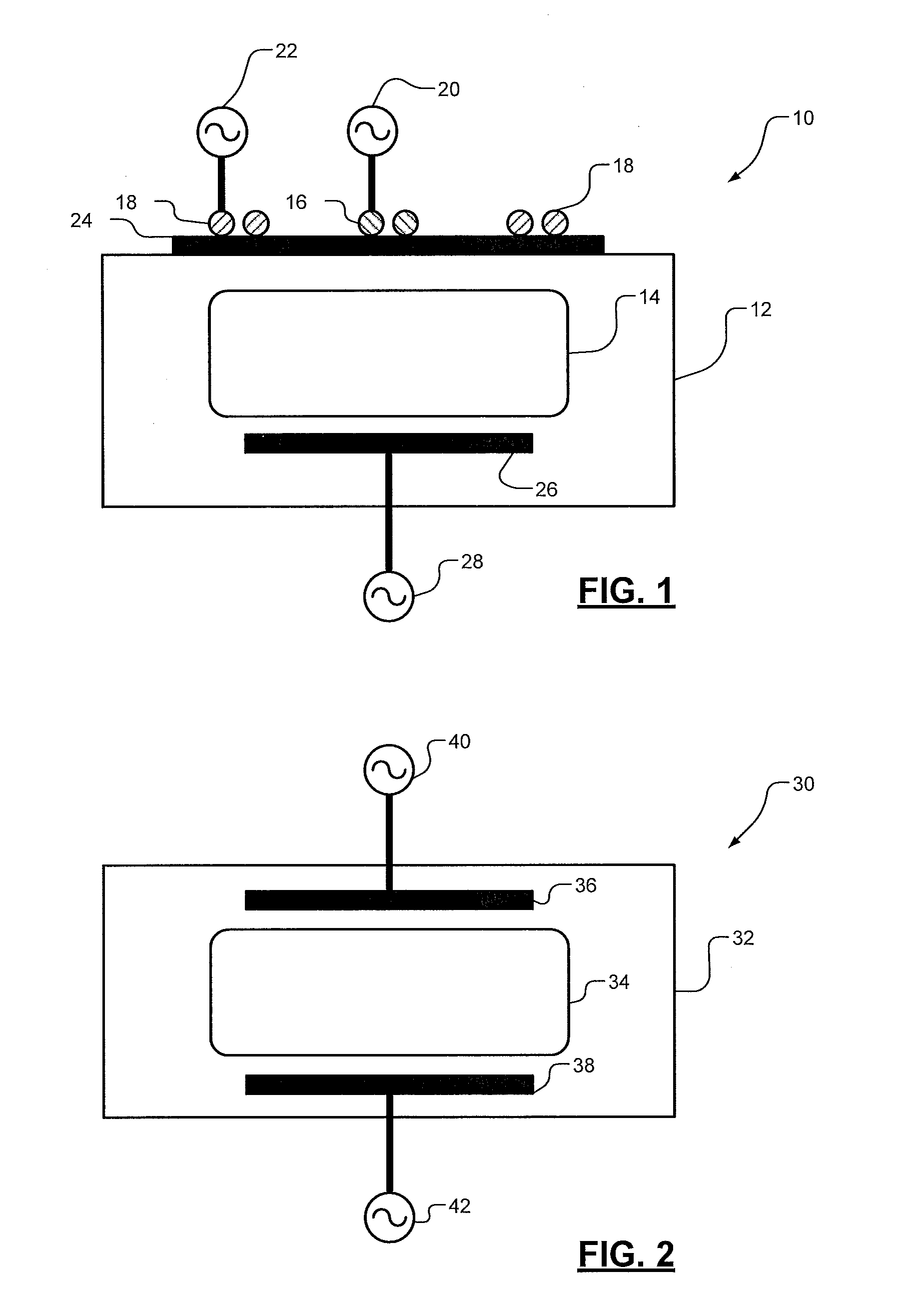
[0038]FIG. 1 depicts an exemplary representation of an inductively coupled plasma (ICP) system 10. ICP system 10 includes a plasma chamber 12 for generating plasma 14. Power in the form of voltage or current is applied to plasma chamber 12 via a pair of coils, including an inner coil 16 and an outer coil 18. Power is applied to inner coil 16 via a RF power source 20, and power is applied to outer coil 18 via a RF generator or power source 22. Coils 16 and 18 are mounted to a dielectric window 24 that assists in coupling power to plasma chamber 12. A substrate 26 is placed in plasma chamber 12 and typically forms the work piece that is the subject of plasma operations. A RF generator or power source 28 applies power to plasma chamber 12 via substrate 26. In various configurations, the RF power sources 20, 22 provide a bias voltage or current to ignite or generate plasma 14. Also in ...


PUM


Abstract

A system for controlling RF power supplies applying power to a load, such as a plasma chamber, includes a master power supply and a slave power supply. The master power supply provides a control signal, such as a frequency and phase signal, to the slave power supply. The slave power supply receives the frequency and phase signal and also receives signals characteristic of the spectral emissions detected from the load. The slave RF power supply varies the phase and power of its RF output signal applied to the load. Varying the power controls the width of an ion distribution function, and varying the phase controls a peak of the ion distribution. Depending upon the coupling between the RF generators and the load, different spectral emissions are detected, including first harmonics, second harmonics, and, in the case of a dual frequency drive system, intermodulation distortion.

Description

FIELD[0001]The present disclosure relates to RF generator systems and to RF generator control systems.BACKGROUND[0002]The background description provided here is for the purpose of generally presenting the context of the disclosure. Work of the presently named inventors, to the extent it is described in this background section, as well as aspects of the description that may not otherwise qualify as prior art at the time of filing, are neither expressly nor impliedly admitted as prior art against the present disclosure.[0003]Plasma etching is frequently used in semiconductor fabrication. In plasma etching, ions are accelerated by an electric field to etch exposed surfaces on a substrate. The electric field is generated based on RF power signals generated by a radio frequency (RF) generator of a RF power system. The RF power signals generated by the RF generator must be precisely controlled to effectively execute plasma etching.[0004]A RF power system may include a RF generator, a mat...

Claims


Application Information

Patent Timeline
Patent Type & Authority Applications(United States)
IPC IPC(8): H01J37/32
CPCH01J37/32155H01J37/32091H01J37/321H01J2237/334H01J37/32165H01J37/3299H01J37/32972H01J37/32082H01J37/32119H01J37/32137H01J37/32174
Inventor COUMOU, DAVID J.REINHARDT, ROSSELNER, YUIRYGILL, DANIEL M.PHAM, RICHARD
Owner MKS INSTR INC
Why Eureka
Try Eureka