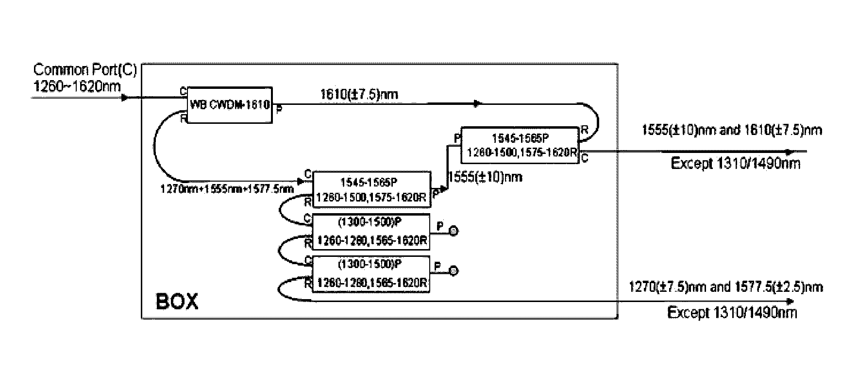
Optical transceiver module with dual band pass WDM coupler embedded therein
a dual-band pass, optical transceiver technology, applied in multiplex communication, instruments, optical elements, etc., can solve the problem of not revealing a method capable of increasing the reliability of bidirectional optical transmission and reception, and achieve the effect of reducing the size of the optical transceiver module, preventing the increase of the optical insertion loss of the pass band, and saving costs
Active Publication Date: 2017-03-02
LIGHTRON FIBER OPTIC DEVICES
View PDF23 Cites 9 Cited by
- Summary
- Abstract
- Description
- Claims
- Application Information
AI Technical Summary
Benefits of technology
The present invention provides an optical transceiver module with a dual band pass WDM coupler that selectively passes the wavelengths of the transmission and optical signal input through the common port. This eliminates the need for multiple stages of WDM couplers, reducing the size and cost of the module, and preventing optical insertion loss. The coupler also prevents cross-talk and improves reliability for bidirectional optical transmission and reception. Additionally, an optical filter unit may be added to further increase reliability and decrease ripple in the pass band. Overall, this invention enables a more efficient and reliable optical transceiver for bidirectional optical transmission and reception.
Problems solved by technology
However, Patent Document 1 merely discloses only a method capable of increasing optical coupling efficiency between a laser diode TO-Can and a GRIN lens by disposing a parallel optical lens between laser diode TO-Can and the GRIN lens, and does not disclose a method capable of increasing reliability of a bidirectional optical transmission and reception by providing the pass band for selectively passing two different wavelengths (i.e., a wavelength of a transmission signal and a wavelength of a reception signal).
Method used
View moreImage
Smart ImageViewing Examples
Examples
Embodiment Construction
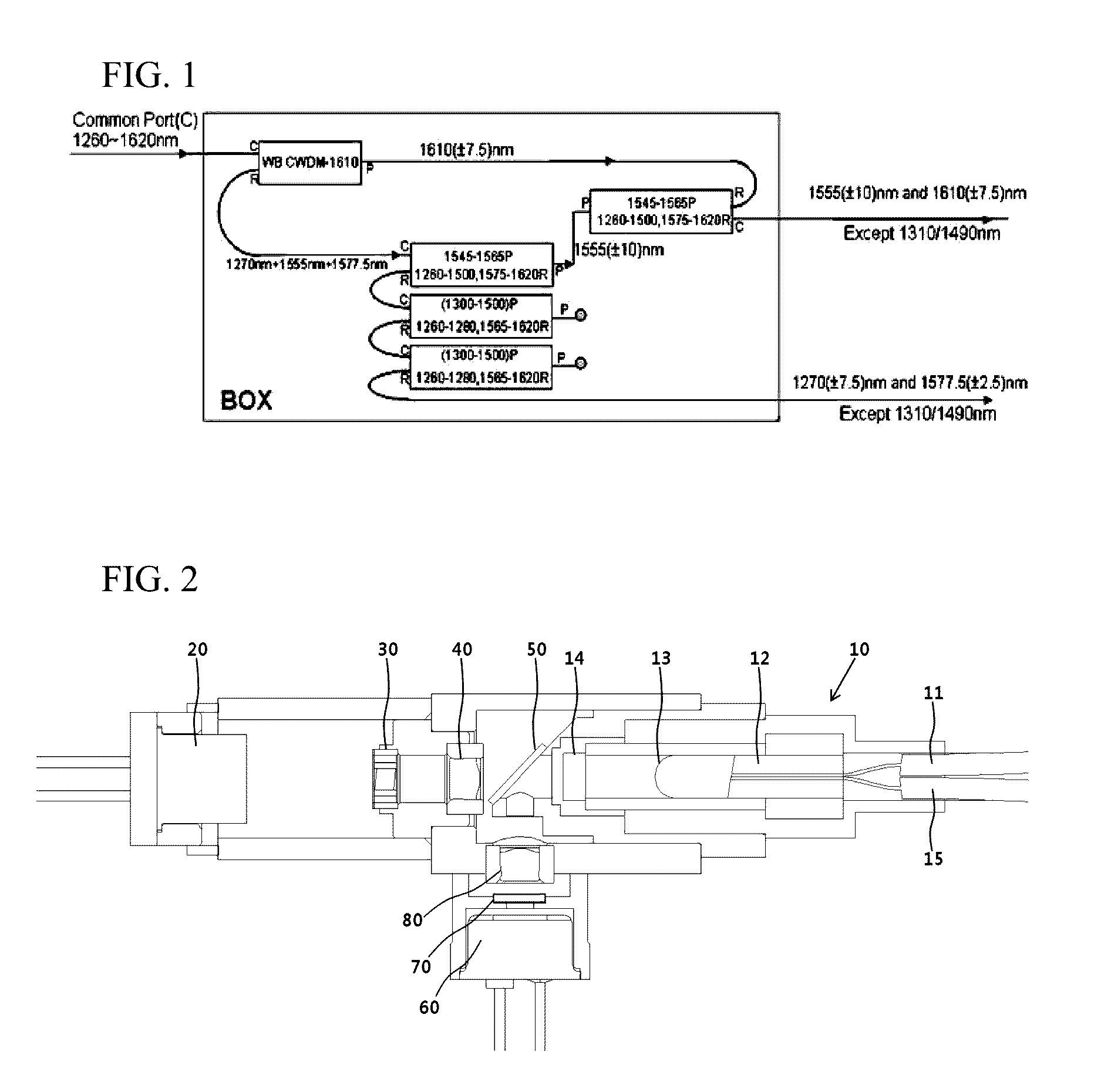
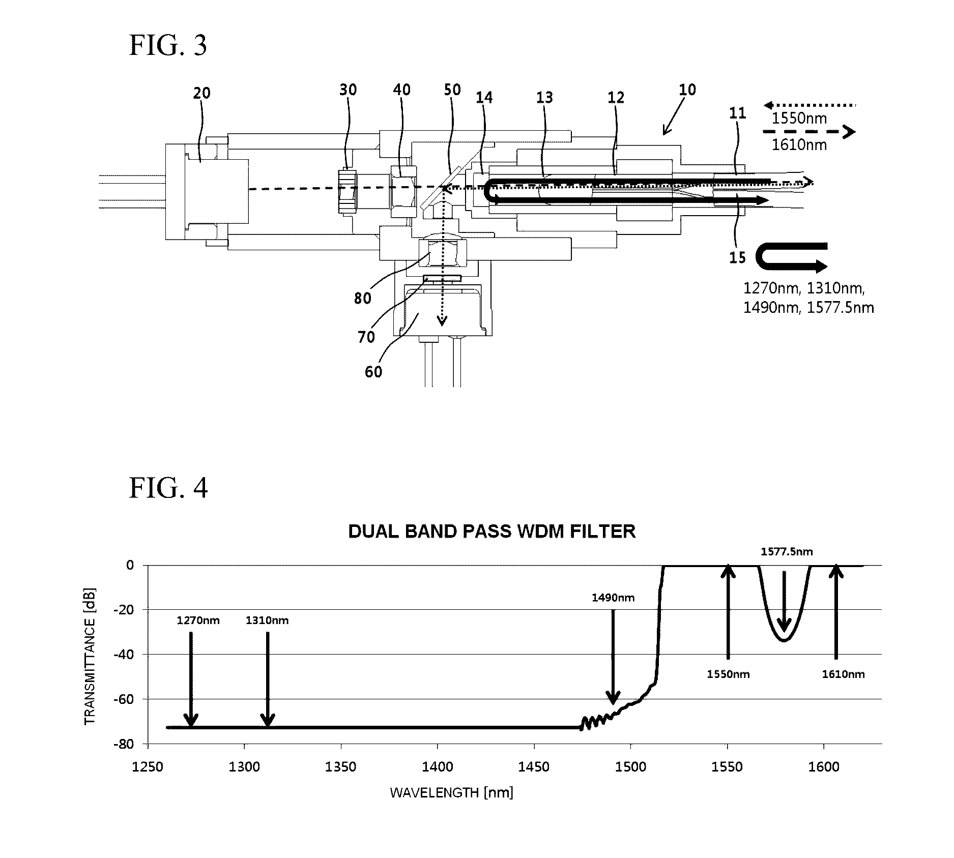
[0071]10: dual pass band WDM coupler[0072]11: common port[0073]12: dual core capillary[0074]13: C lens[0075]14: dual band pass WDM filter[0076]15; reflection port[0077]20: optical transmitting unit[0078]30: optical isolator[0079]40: parallel light lens[0080]50: WDM filter[0081]60: optical receiving unit[0082]70: optical filter unit for optical reception[0083]80: condensing lens
Login to View More PUM
 Abstract
Provided is an optical transceiver module having a dual band pass WDM coupler embedded therein, wherein the dual band pass WDM coupler provides pass bands for selectively passing a transmission signal output from an optical transmitting unit, and an optical signal having a specific wavelength received by an optical receiving unit among optical signals input through a common port. According to the present invention, a size and cross-talk of the optical transceiver module may be reduced, and the optical transceiver module may be used as a video transceiver in an optical subscriber network according to an ITU-RG.983.3 standard.
Description
TECHNICAL FIELD[0001]The present invention relates to an optical transceiver module having a dual band pass wavelength division multiplexing (WDM) coupler embedded therein, and more particularly, to an optical transceiver module having a dual band pass WDM coupler embedded therein, wherein the dual band pass WDM coupler provides pass bands for selectively passing a transmission signal output from an optical transmitting unit, and an optical signal having a specific wavelength received by an optical receiving unit among optical signals input through a common port.BACKGROUND ART[0002]In order to satisfy a demand on data traffic which is recently increased, and a demand on various multimedia services such as a smart mobile phone, a high performance television (e.g., high definition TV, a 3D TV, a smart TV, etc.), an electronic commerce, a video on demand (VOD), and the like, it is required to extend capacity of an existing optical communication network.[0003]For this reason, a waveleng...
Claims
Login to View More Application Information
Patent Timeline
 Patent Type & Authority Applications(United States)
IPC IPC(8): H04J14/02G02B6/42G02B6/32H04B10/40G02B6/293
CPCH04J14/02H04B10/40G02B6/29361G02B6/4206G02B6/2938G02B6/4246G02B6/32G02B6/4203G02B6/4215H04J14/0209H04J14/0213G02B6/00H04B10/071
Inventor LEE, DONG-HYUNCHOI, JIN-SOOKWON, YOON-KOO
Owner LIGHTRON FIBER OPTIC DEVICES
Features
- R&D
- Intellectual Property
- Life Sciences
- Materials
- Tech Scout
- Unparalleled Data Quality
- Higher Quality Content
- 60% Fewer Hallucinations
Learn More Browse by: Latest US Patents, China's latest patents, Technical Efficacy Thesaurus, Application Domain, Technology Topic, Popular Technical Reports.
© 2025 PatSnap. All rights reserved.Legal|Privacy policy|Modern Slavery Act Transparency Statement|Sitemap|About US| Contact US: help@patsnap.com


