
Process for producing synthesis gas

a technology of synthesis gas and process, which is applied in the direction of hydrogen/synthetic gas production, chemistry apparatus and processes, inorganic chemistry, etc., can solve the problems of increasing the required heat transfer area of the heat exchange reformer, the combination is counterintuitive, and the apparatus cost is increased, so as to reduce the cost of equipment and reduce the capital cost. , the effect of reducing the cost of equipmen

Active Publication Date: 2017-03-09
HALDOR TOPSOE AS
View PDF0 Cites 0 Cited by
  • Summary
  • Abstract
  • Description
  • Claims
  • Application Information

AI Technical Summary

Benefits of technology

The present invention provides a solution to the problem of metal dusting in the heat exchange reformer while maintaining high efficiency and low capital cost. This is achieved by combining the effluent from the ATR with the reformed gas from the catalyst side of the HER in a specific ratio. This ratio reduces the temperature of the synthesis gas entering the HER, which in turn reduces the driving force for heat transfer in the HER and the required heat transfer area of the heat exchange reformer. The invention also allows for the use of more inexpensive materials in the heat exchange reformer and reduces the risk of metal dusting. Additionally, carbon dioxide can be removed from the second portion of raw synthesis gas to improve the efficiency of FT-synthesis.

Problems solved by technology

It is however counterintuitive to combine only part of the effluent from the ATR with the effluent from the HER.
This leads to an increase in the required heat transfer area of the heat exchange reformer and consequently increased cost of the apparatus.

Method used


Image

  • Process for producing synthesis gas
  • Process for producing synthesis gas
  • Process for producing synthesis gas

Examples


example 1

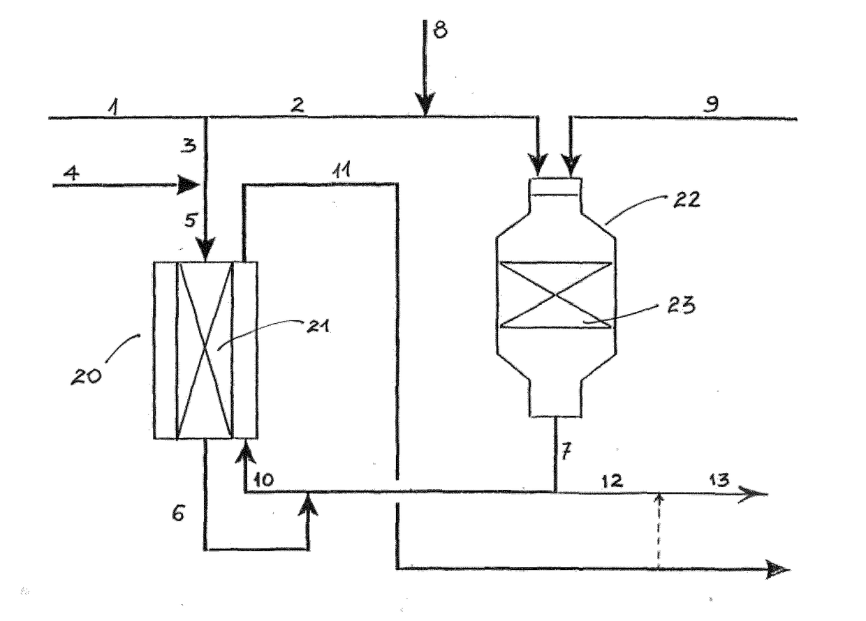
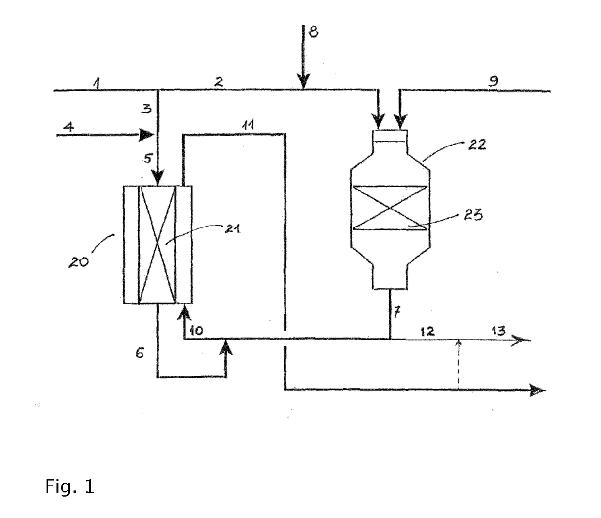
[0055]Calculations have been made to simulate the synthesis gas section of a Gas-to-Liquids facility according to the invention as described herein and with reference to the accompanying figure. Natural gas (NG) mixed with steam is used as feed (stream 1). 10% of the feed is sent to the heat exchange reformer (line 3). Additional steam is added to give a steam-to-carbon ratio of the heat exchange reformer feed of 3.5. The remaining part of the feed is mixed with tail gas (line 8) from a Fischer-Tropsch synthesis section for production of liquid hydrocarbons and passed to the ATR. The amount of steam in the feed (line 1) is adjusted such that the S / C-ratio in the feed to the ATR is 0.6. The amount of tail gas added in line 8 is adjusted to provide an H2 / CO-ratio downstream the ATR (line 7) of 2.00. Oxygen is also added to the ATR through line 9. The process conditions are designed to provide an exit temperature of 1025° C. from the ATR.

[0056]Part of the exit stream (line 7), i.e. raw...

example 2

[0060]Calculations have been made to simulate the synthesis gas section of a methanol plant according to the invention as described herein and with reference to the accompanying figure. The parameters have been set to the same values as in Example 1 with the exception that the S / C-ratio in the feed to the ATR is 0.4. The only other difference from the parameters given in Example 1 is that no tail gas is added, i.e. volumetric flow in stream 8 is zero.

[0061]In methanol it is desired to have a so-called module of ca. 2. The module is defined as:

[0062](FH2−FCO2) / (FCO+FCO2), where FX is the flow of component X.

[0063]The results of the calculations are shown in the table below. It is seen that the thermodynamic potential of metal dusting decreases when the bypass ratio is increased.

CO reductionQa2)Bypass ratio1) %bar00.0444200.0485600.0674700.07901)% of ATR effluent gas bypassing heat exchange reactor: stream 12 / stream 72)Qa = PH2O / (PCO * PH2) for the CO reduction CO + H2 = C + H2O, reac...


PUM

PropertyMeasurementUnit
molar ratioaaaaaaaaaa

Abstract

Process for the production of synthesis gas by catalytic steam reforming of a hydrocarbon containing feedstock in parallel in an autothermal steam reformer and heat exchange reformer, the heat for the steam reforming reactions in the heat exchange reformer being provided by indirect heat exchange with the combined effluent of the heat exchange reformer and a portion of the autothermal steam reformer.

Description

FIELD OF THE INVENTION[0001]The present invention relates to a process for production of synthesis gas used especially for the production of liquid hydrocarbons such as diesel by Fischer-Tropsch synthesis, methanol, or gasoline. The invention relates in particular to a process for the production of synthesis gas in which part of the hydrocarbon feed is passed through a first reforming process line comprising autothermal reforming (ATR) while the remaining minor portion of the hydrocarbon feed is passed through a second reforming process line comprising heat exchange reforming and in which a portion of the effluent gas from the autothermal reformer is used to provide heat for the steam reforming in the heat exchange reformer by indirect heat exchange.BACKGROUND OF THE INVENTION[0002]A typical plant for production of gasoline, liquid hydrocarbons such as diesel, or methanol from for example natural gas typically comprises of the following main process units: (a) air separation, (b) sy...

Claims


Application Information

Patent Timeline
Patent Type & Authority Applications(United States)
IPC IPC(8): C01B3/38
CPCC01B3/382C01B3/384C01B3/386C01B2203/0233C01B2203/0244C01B2203/82C01B2203/0844C01B2203/0883C01B2203/1235C01B2203/141C01B2203/0261C01B2203/04C01B2203/0475C01B2203/062C01B2203/142C01B2203/148
Inventor AASBERG-PETERSEN, KIMDYBKJ.AE BUTTED.R, IB
Owner HALDOR TOPSOE AS
Learn More