Eureka AIR delivers breakthrough ideas for toughest innovation challenges, trusted by R&D personnel around the world.

Method of manufacturing a pipe segment

Active Publication Date: 2017-03-09
ITP
View PDF18 Cites 4 Cited by
  • Summary
  • Abstract
  • Description
  • Claims
  • Application Information

AI Technical Summary

Benefits of technology

This patent text describes a new manufacturing method for double-walled pipe segments that have several advantages. Firstly, these pipe segments can be easily screwed together without needing additional protection, and can be installed directly in the open sea. Secondly, the methods used to assemble double-walled pipe segments are very similar to the methods used for single-walled pipe segments. Thirdly, the double-walled pipe segments have a longer life when stored and even after installation, as their mechanical and thermal insulation characteristics are preserved. Fourthly, the female bayonet-piece makes it easier to provide guiding during the screwing-together process. Overall, this patent describes a more efficient and reliable method for manufacturing and installing double-walled pipe segments in drilling rigs.

Problems solved by technology

A drawback suffered by the technique of implementing floor-to-surface link tubes by using a protective marine riser is that it is a particularly lengthy technique.
Thus, this first technique cannot be used effectively in emergency situations such as, for example, collecting hydrocarbon leaks coming from a subsea well or from equipment installed at great depths.
However, a drawback is that such second assembly technique does not make it possible to provide thermal insulation that is effective.
Thus, irreversible stoppages can occur due to formation of blockages of paraffin or of methane hydrate.
The lower the temperature of the subsea hydrocarbon well and the deeper the floor-to-surface link tubes goes, the more frequent that type of failure is, since the floor-to-surface link tube then suffers major heat losses.

Method used


Image

  • Method of manufacturing a pipe segment
  • Method of manufacturing a pipe segment
  • Method of manufacturing a pipe segment

Examples


Embodiment Construction

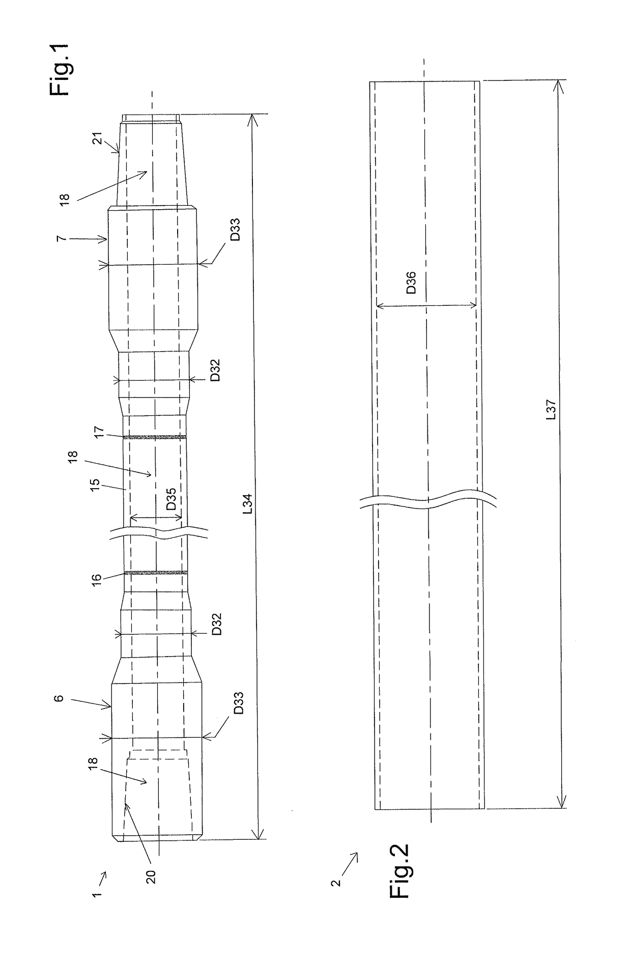
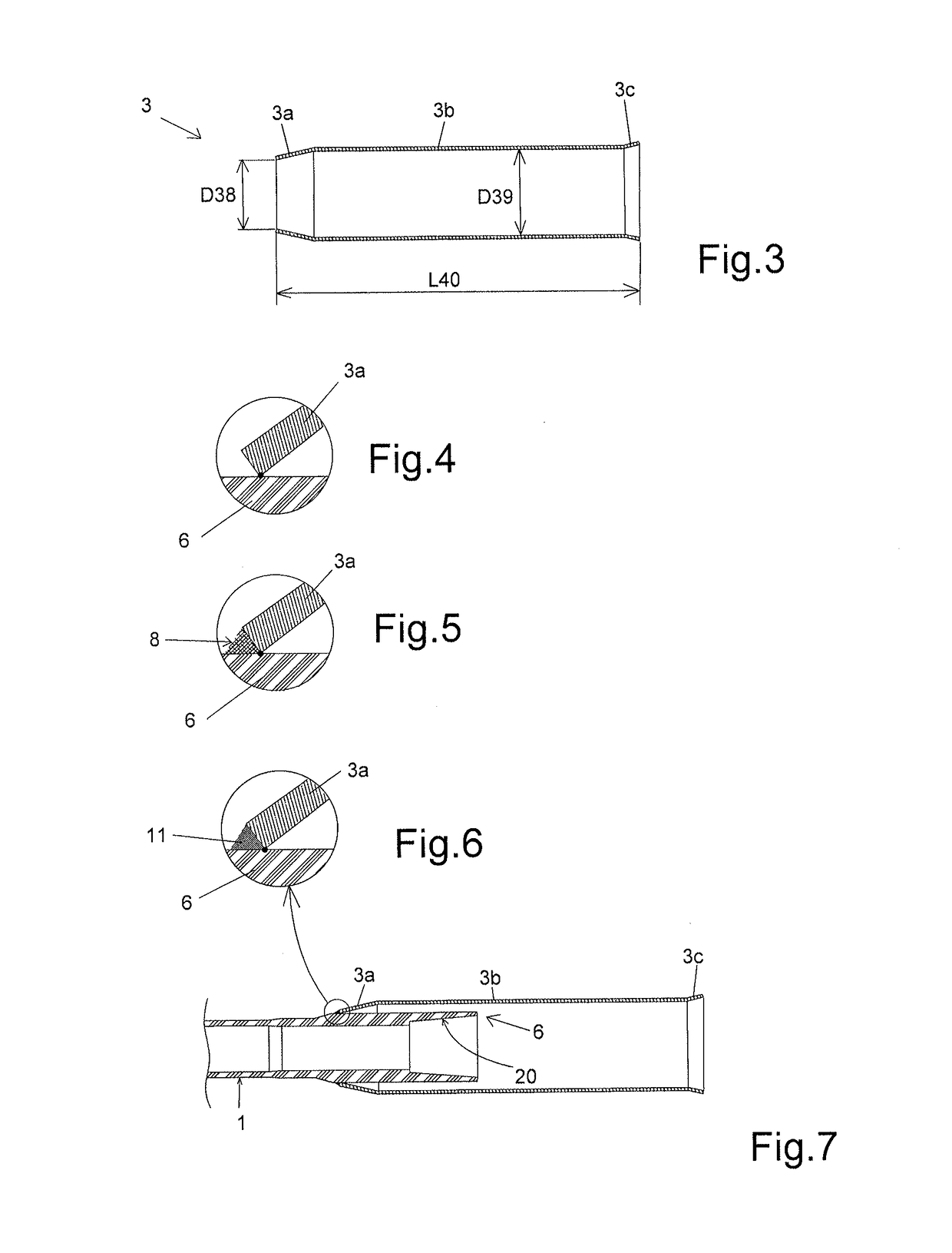
[0058]The invention is described in more detail below. An example of a method of manufacturing a double-walled pipe segment is shown in FIG. 14. The manufacturing steps and the elements used for the manufacturing are described in detail below with reference to FIGS. 1 to 11.

[0059]FIG. 1 is a side view of a connection and transport pipe segment 1. This pipe segment 1 comprises a central tube 15 in which the transport pipe 18 is formed that opens out at the two ends of the pipe segment 1. For example, the inside diameter D35 of the transport pipe 18 lies in the range 120 millimeters (mm) to 140 mm.

[0060]The central tube 15 is secured to two portions 6 and 7 forming the two reinforced ends 6 and 7 of the pipe segment 1. This securing is obtained by two friction welds 16 and 17. The reinforced ends 6 and 7 are also referred to as “tool joints”.

[0061]For example, the central tube 15 is made of steel having high yield strength greater than or equal to 95 ksi, and preferably greater than o...


PUM


Abstract

The invention relates to a method of manufacturing a pipe segment for a link tube between the sea floor and a petroleum drilling rig disposed on the sea surface, wherein it consists in:providing a transport pipe segment that is resistant to open-sea conditions;disposing a female bayonet-piece around one reinforced end of the transport pipe segment;welding or otherwise bonding a narrower portion of the bayonet-piece to said reinforced end;disposing an insulator around the transport pipe segment and around the bayonet-piece;inserting the transport pipe segment into an outer wall segment;welding or otherwise bonding a narrower portion of the outer wall segment to the other reinforced end of the transport pipe segment;disposing a cover-piece around the bayonet-piece;welding or otherwise bonding the cover-piece to the outer wall segment and to the bayonet-piece;it being possible to apply tightening torque to the outer wall segment and to transmit it to the transport pipe segment.

Description

BACKGROUND OF THE INVENTION[0001]1. Field of the Invention[0002]The present invention relates to the technical field of link tubes between the sea floor and a petroleum rig disposed on the sea surface, such floor-to-surface link tubes being used to transport hydrocarbons from the sea floor to the sea surface.[0003]2. Description of the Related Art[0004]Floor-to-surface link tubes can be installed from a petroleum rig out at sea, and can reach a height of 1,000 meters (m) or indeed of 3,000 m. Such floor-to-surface link tubes must thus have particularly high traction strengths in order to withstand not only their own weights but also the torsion and transverse forces exerted by marine currents. In addition, a floor-to-surface link tube installed at a great depth must also withstand the surrounding water pressure.[0005]A first technique consists in installing a transport pipe in a protective riser, also known as a “marine drilling riser”. The space between the riser and the transport ...

Claims


Application Information

Patent Timeline
IPC IPC(8): F16L13/02F16L59/02
CPCF16L59/028F16L13/0209E21B17/017E21B17/042F16L39/005F16L59/143F16L59/20F16L9/18F16L15/002F16L15/08F16L59/182
Inventor OLLIER, PIERREDAMOUR, JEAN-AURELIEN
Owner ITP
Why Eureka
Eureka Blog
Learn More