Free space optical receiver and free space optical receiving method

Active Publication Date: 2017-03-09
NEC CORP
View PDF43 Cites 7 Cited by
  • Summary
  • Abstract
  • Description
  • Claims
  • Application Information

AI Technical Summary

Benefits of technology

[0017]According to a free space optical receiver and a free space optical receiving method of the present invention, it is possible to effective

Problems solved by technology

In a free space optics (FSO) receiver, a wave-front distortion of laser light due to atmospheric propagation becomes a problem as described below.
In the free space optics (FSO) receiver, optical coupling with a singl

Method used


Image

  • Free space optical receiver and free space optical receiving method
  • Free space optical receiver and free space optical receiving method
  • Free space optical receiver and free space optical receiving method

Examples


first exemplary embodiment

A First Exemplary Embodiment

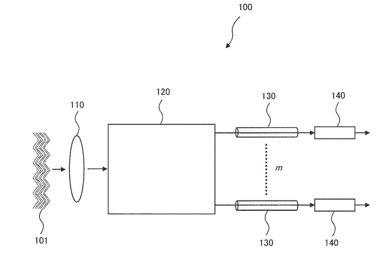
[0030]FIG. 1 is a block diagram illustrating a configuration of a free space optical receiver 100 in accordance with a first exemplary embodiment of the present invention. The free space optical receiver 100 includes light collecting means 110 for collecting laser light 101 having propagated through a free space transmission path, mode controlling means 120, a plurality of single mode transmission media 130, and a plurality of light receiving means 140.

[0031]The mode controlling means 120 separates the laser light collected by the light collecting means 110 into a plurality of propagation mode beams depending on the wave-front fluctuation of the laser light and outputs the propagation mode beams. Each of the single mode transmission media 130 guides one of the plurality of propagation mode beams. Each of the light receiving means 140 receives one of the plurality of propagation mode beams through the single mode transmission media 130. In FIG. 1, the numb...

second exemplary embodiment

A Second Exemplary Embodiment

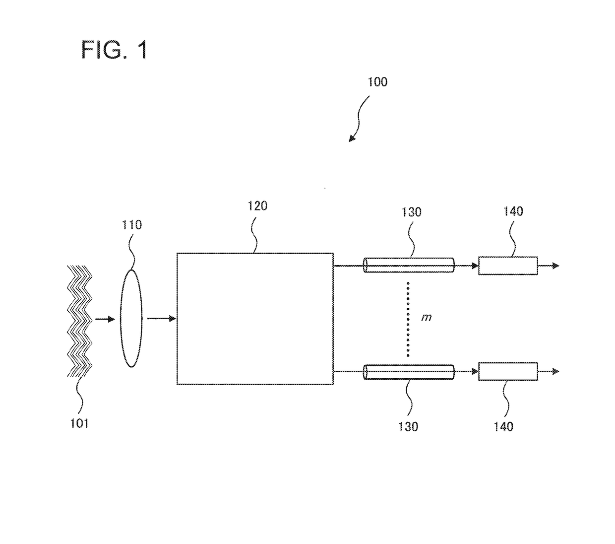
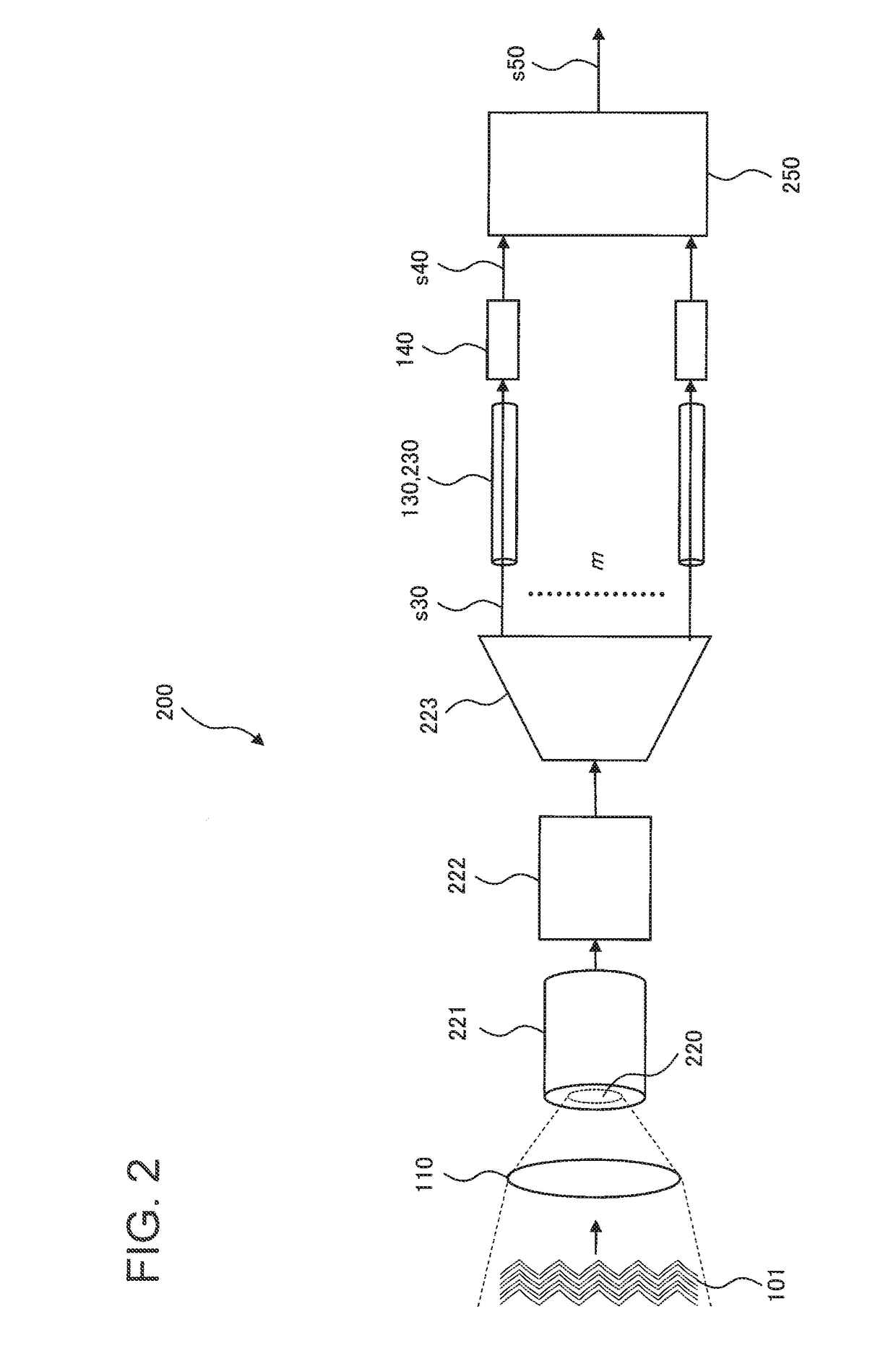
[0038]Next, a second exemplary embodiment of the present invention will be described. FIG. 2 is a block diagram illustrating a configuration of a free space optical receiver 200 in accordance with the second exemplary embodiment of the present invention.

[0039]The free space optical receiver 200 includes light collecting means 110 for collecting laser light 101 having propagated through a free space transmission path, a multimode transmission medium 221, mode converting means 222, and mode separating means 223. The multimode transmission medium 221, the mode converting means 222, and the mode separating means 223 compose mode controlling means. The mode controlling means produces multimode beams from laser light and produces a plurality of propagation mode beams obtained by converting high-order mode beams included in the multimode beams into low-order mode beams by controlling the multimode beams.

[0040]The free space optical receiver 200 further includes...

third exemplary embodiment

A Third Exemplary Embodiment

[0074]Next, a third exemplary embodiment of the present invention will be described. FIG. 4 is a block diagram illustrating a configuration of a free space optical receiver 300 in accordance with the present exemplary embodiment.

[0075]The free space optical receiver 300 includes light collecting means 110, a multimode transmission medium 221, mode converting means 222, mode separating means 223, single mode fibers 230 as a plurality of single mode transmission media, a plurality of light receiving means 140, and signal processing means 250. The above-described configurations are similar to those of the free space optical receiver 200 according to the second exemplary embodiment.

[0076]The free space optical receiver 300 according to the present exemplary embodiment differs from the free space optical receiver 200 according to the second exemplary embodiment in controlling a mode converting function dynamically in combination with monitoring means. That is ...


PUM


Abstract

It is impossible to prevent the deterioration of the coupling efficiency between received light and a single mode fiber, and difficult to achieve a higher transmission rate, with respect to a free space optical communication receiver; therefore, a free space optical receiver according to an exemplary aspect of the present invention includes light collecting means for collecting laser light having propagated through a free space transmission path; mode controlling means for separating the laser light collected by the light collecting means into a plurality of propagation mode beams depending on a wave-front fluctuation of the laser light and outputting the propagation mode beams; a plurality of single mode transmission media for guiding the plurality of propagation mode beams, respectively; and a plurality of light receiving means for receiving the plurality of propagation mode beams respectively through the plurality of single mode transmission media.

Description

TECHNICAL FIELD[0001]The present invention relates to free space optical receivers and a free space optical receiving methods, in particular, to a free space optical receiver and a free space optical receiving method to perform optical communication using a laser light beam propagating through a free space.BACKGROUND ART[0002]In recent years, by the development of remote sensing technologies, observational instruments mounted in aircraft and artificial satellites have grown in performance, and the amount of information transmitted from the air to the ground is increasing. In order to cope with further performance improvement of the observational instruments in the future, data communication technologies that use free space optics (FSO) have been aggressively studied that uses optical frequency bands unconstrained by radio frequency bands. The achievement of the high-capacity free space optics (FSO) requires a high-speed technology for a transmission rate and a wavelength multiplexin...

Claims


Application Information

Patent Timeline
IPC IPC(8): H04B10/112H04B10/60
CPCH04B10/60H04B10/1121H04J14/02
Inventor TAKAHASHI, SEIGOITO, TOSHIHARUHOSOKAWA, KOHEI
Owner NEC CORP
Why Eureka
Try Eureka