
Spacer fabric, spacer fabric section and heatable covering element

a technology of spacer fabric and heat-absorbing covering element, which is applied in the field of spacer fabric, can solve the problems of considerable irregularities in the spacer fabric, limited use possibilities of described spacer fabric provided with heating wires, and relatively complex contact, etc., and achieves optimal drapeability and manufacture, good heating properties, and high elasticity and adaptability.

Inactive Publication Date: 2017-03-09
MULLER TEXTIL
View PDF7 Cites 5 Cited by
  • Summary
  • Abstract
  • Description
  • Claims
  • Application Information

AI Technical Summary

Benefits of technology

The invention provides a spacer fabric that is easy to make and has good functional properties. Additionally, a spacer fabric section and a heatable covering element made from this fabric are also provided. The spacer fabric has elasticity and adaptability, good heating properties, and can be easily shaped for different applications. Its manufacturing process is simple compared to existing embodiments.

Problems solved by technology

The contacting is relatively complex, wherein, in addition, the possibilities for using the described spacer fabric provided with heating wires are limited.
This results in the disadvantage, however, that a further, complex method step is required, wherein yarns that have been incorporated by embroidery techniques can result in considerable irregularities in the spacer fabric.
In the case of the described textile materials in particular, bonding is frequently difficult due to the open textile structure, wherein the additional lamination adhesives can result in unpleasant odors during use and in increased effort with respect to disposal or recycling.
This textile material also is difficult to manufacture, without any cushioning effect.
This is due, in particular, to the fact that suitable material could not be manufactured in a satisfying level of quality with a justifiable amount of effort.

Method used


Image

  • Spacer fabric, spacer fabric section and heatable covering element
  • Spacer fabric, spacer fabric section and heatable covering element
  • Spacer fabric, spacer fabric section and heatable covering element

Examples


Embodiment Construction

[0063]The following is a detailed description of example embodiments of the invention depicted in the accompanying drawing. The example embodiments are presented in such detail as to clearly communicate the invention and are designed to make such embodiments obvious to a person of ordinary skill in the art. However, the amount of detail offered is not intended to limit the anticipated variations of embodiments; on the contrary, the intention is to cover all modifications, equivalents, and alternatives falling within the spirit and scope of the present invention, as defined by the appended claims.

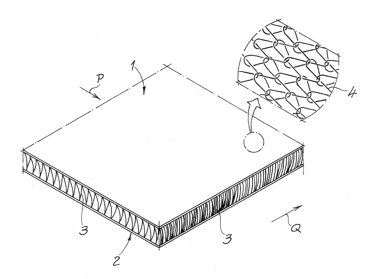
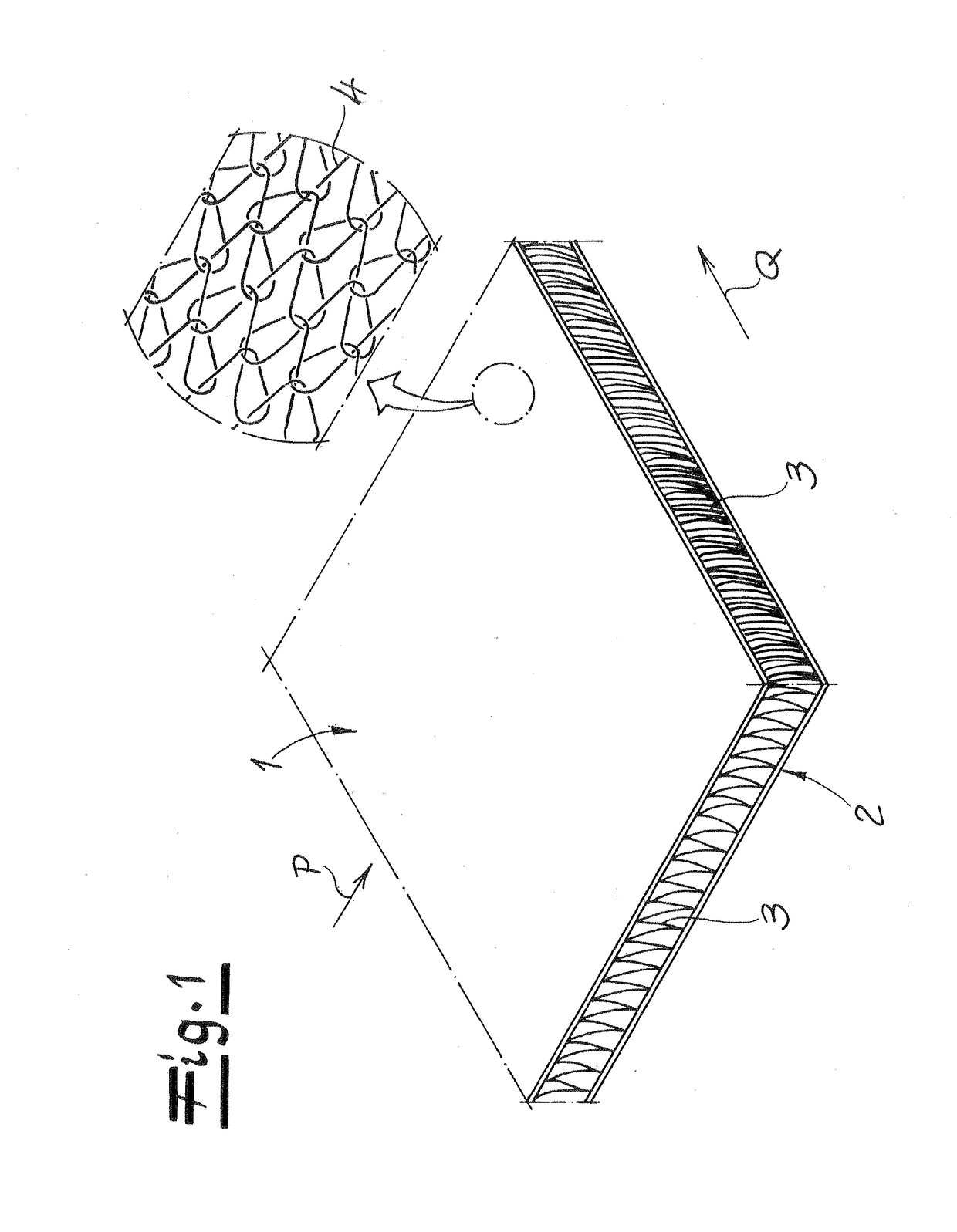
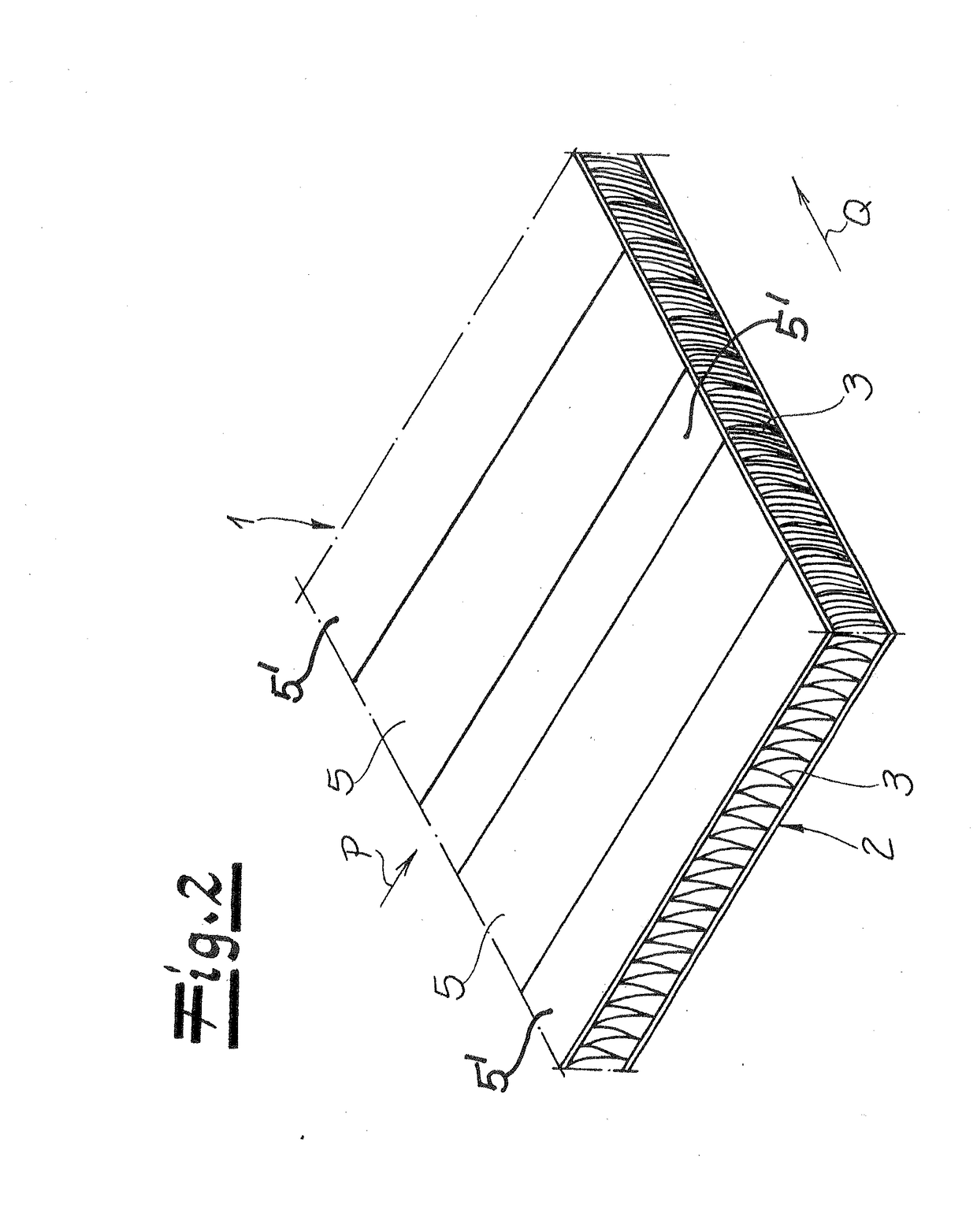
[0064]FIG. 1 shows the basic design of a spacer fabric according to the invention, comprising a first flat layer of knitted fabric 1, a second flat layer of knitted fabric 2, and spacer threads 3 connecting the layers of knitted fabric 1, 2. The first layer of knitted fabric 1 comprises conductive threads 4, which are further described in the following in association with FIG. 3.

[0065]Accord...


PUM


Abstract

A spacer fabric has a first flat layer of knitted fabric formed with conductive threads, a second flat layer of knitted fabric and spacer threads connecting the first and second layers of knitted fabric. The conductive threads have an electrically conductive coating and are arranged adjacent to one another over an entire surface in the first layer or in conductive strips extending along a direction of production, and are connected to one another in direct, electrical contact. The conductive threads preferably are formed from a plastic multifilament yarn provided with a coating and have a fineness of less than 250 dtex. The conductive threads in the first layer of knitted fabric form loops with a stitching over at least two wales. The portion of the conductive coating is less than 50% by weight of the conductive threads.

Description

CROSS-REFERENCE TO A RELATED APPLICATION[0001]The invention described and claimed hereinbelow is also described in German Patent DE 10 2015 12 114 778.5, filed on Sep. 3, 2015. This German Patent Application, subject matter of which is incorporated herein by reference, provides the basis for a claim of priority of invention under 35 U.S.C. 119(a)-(d).BACKGROUND OF THE INVENTION[0002]The invention relates to a spacer fabric having a first flat layer of knitted fabric comprising conductive threads, a second flat layer of knitted fabric and spacer threads connecting the layers of knitted fabric; the conductive threads comprise an electrically conductive coating and are arranged adjacent to one another over an entire surface in the first layer of knitted fabric or in conductive strips extending along a direction of production, and are connected to one another in direct, electrical contact.[0003]Various approaches are known for providing a spacer fabric with electrical conductors, in par...

Claims


Application Information

Patent Timeline
Patent Type & Authority Applications(United States)
IPC IPC(8): H05B3/34
CPCH05B2203/013H05B3/345H05B2203/026H05B2203/029
Inventor MUELLER, STEFANMUELLER, FRANK
Owner MULLER TEXTIL
Learn More