
Method of Installing a Percutaneous Device

a percutaneous device and intracorporeal technology, applied in the field of intracorporeal portion or intracorporeal component of a percutaneous device, can solve the problems of affecting the maintenance of healthy tissues, uncomfortable wear and use, and difficulty in reliably secure shoulder/hip disarticulation prostheses for patients,

Active Publication Date: 2017-03-16
STANMORE IMPLANTS WORLDWIDE
View PDF0 Cites 0 Cited by
  • Summary
  • Abstract
  • Description
  • Claims
  • Application Information

AI Technical Summary

Benefits of technology

The invention is a percutaneous device that allows for the attachment of an external limb prosthesis to a patient's skeleton without rigidly fixing the device to the bone. The device includes an articulating surface that can pivot relative to the patient's bone, allowing for a more natural coupling of the prosthesis. The device also includes an intracorporeal component with a non-circular flange that provides rotational stability to the socket of the prosthesis and prevents spinning. The technical effects of the invention include improved stability and mobility of the external limb prosthesis and reduced pain and discomfort for the patient.

Problems solved by technology

It is therefore difficult and cumbersome to reliably secure shoulder / hip disarticulation prostheses to patients.
Such hip and shoulder disarticulation prostheses are uncomfortable to wear and use and suffer from numerous problems at the skin-socket interface.
Focal points of increased stress caused by non-uniform pressure distribution can lead to skin-related complications, whilst the unnatural microbial environment generated in the socket is detrimental to the maintenance of healthy tissues.
Furthermore, disarticulation exoprostheses are difficult to secure to a patient and can be unstable.
Even in transhumeral or transfemoral amputation, where the patient has a humeral or femoral stump to attach an external jointed limb prosthesis to, the patient will still have difficulty using the prosthesis as it is difficult for the patient to control and move the joint(s) of the external prosthesis.
However, such body-powered prostheses are not cosmetically pleasing and are difficult to control.
However, the link is crude and the movements which can be produced are therefore relatively crude.
Such prostheses are also heavy and difficult to use.

Method used


Image

  • Method of Installing a Percutaneous Device
  • Method of Installing a Percutaneous Device
  • Method of Installing a Percutaneous Device

Examples


Embodiment Construction

[0061]The present embodiments represent currently the best ways known to the applicant of putting the invention into practice. But they are not the only ways in which this can be achieved. They are illustrated, and they will now be described, by way of example only.

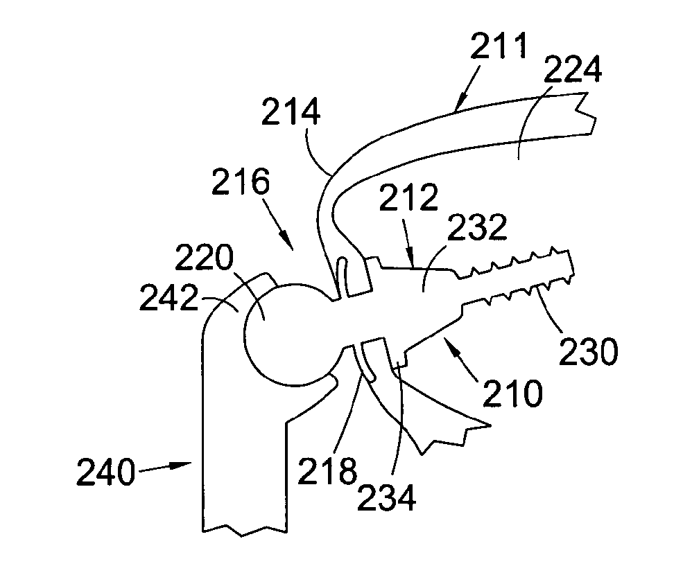
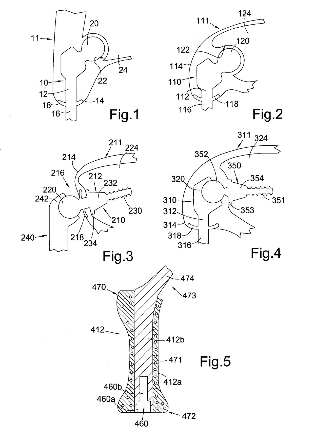
[0062]Referring to FIG. 1, this shows a percutaneous device 10 installed in a subject 11. The percutaneous device 10 has an intracorporeal or subcutaneous portion 12 which resides under the skin 14 when the device is installed and an extracorporeal or external portion 16 which extends from the skin when the device is installed. The device may be made up from separate components connected together, or the components may be formed integrally.

[0063]In FIG. 1, the percutaneous device 10 is shown installed at the subject's hip. The device 10 has a ball component 20 at its proximal end when installed which is received in and articulates with the subject's natural hip socket (the acetabulum) 22 in the subject's pelvis 24. Altern...


PUM


Abstract

An intracorporeal portion of a percutaneous device for a joint disarticulation prosthesis or joint replacement prosthesis, the intracorporeal portion having an extracorporeal portion or having means for rigidly coupling directly to an extracorporeal portion, the extracorporeal portion being for location exterior to the skin, the intracorporeal portion having an articulating component for articulating with an articulating surface, wherein the articulating component is intracorporeal when installed in a human or animal subject.

Description

FIELD OF THE INVENTION[0001]The present invention relates to an intracorporeal portion or intracorporeal component for a percutaneous device for use in a joint disarticulation prosthesis or a joint replacement prosthesis, including shoulder or hip disarticulation prostheses.BACKGROUND TO THE INVENTION[0002]Disarticulation is the amputation of a limb through a joint. Often, disarticulation occurs without the cutting of bone. For example, hip disarticulation is an amputation through the hip joint, removing the entire leg at the hip joint. Shoulder disarticulation is an amputation through the shoulder joint, removing the entire arm at the shoulder joint. Disarticulation is also known as exarticulation.[0003]Amputees who have undergone either disarticulation often wish to be fitted with prosthetic equipment that will allow them to replicate at least a portion of the function of the missing limb.[0004]Unlike in a transhumeral amputation or transfemoral amputation, where the shoulder and ...

Claims


Application Information

Patent Timeline
Patent Type & Authority Applications(United States)
IPC IPC(8): A61F2/78A61F2/38A61F2/60A61F2/54A61F2/64A61F2/32A61F2/40
CPCA61F2/78A61F2/32A61F2/389A61F2/40A61F2002/7887A61F2/64A61F2/605A61F2002/30649A61F2/54A61F2/30749A61F2/38A61F2/4603A61F2/60A61F2/72A61F2002/4619A61F2/2814A61F2/581A61F2/30A61F2/604A61F2/4241
Inventor UNWIN, PAULBLUNN, GORDON
Owner STANMORE IMPLANTS WORLDWIDE
Learn More