Dual Lumen Endobronchial Tube Device

Active Publication Date: 2017-03-16
RGT UNIV OF CALIFORNIA
View PDF5 Cites 25 Cited by
  • Summary
  • Abstract
  • Description
  • Claims
  • Application Information

AI Technical Summary

Benefits of technology

[0014]To aid in correct insertion of the invention dual lumen endotracheal tube designs, the invention may be used with a specialized stylet to create the proper tube orientation and curvature. The stylet is semi-rigid and malleable to aid in tube insertion into the airway, but the stylet distal tip will be more flexible. This design will allow the stylet to point the bronchial lumen tube in the right direction (to a mainstem bronchus of one's choosing) without posing an increased risk of airway rupture or serious injury.
[0015]In another form it will be steerable and will integrate a video chip camera to enable visualization of the airway. This will enable the practitioner to obtain and maintain proper device positioning within the airway.
[0016]In another form of th

Problems solved by technology

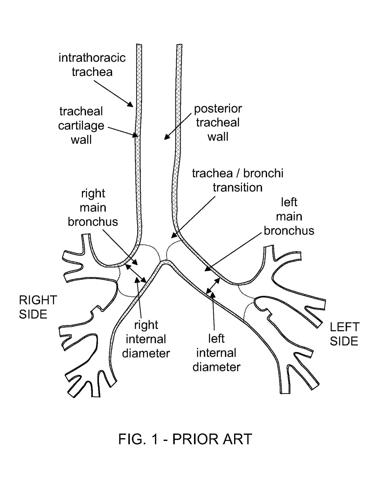
The prior art double lumen endotracheal tube is limited by its large diameter which can unfortunately lead to bronchial damage and even vocal cord scarring, especially when it is left in place for a long period of time.
However, the conventional double lumen endotracheal tube can be associated with significant upper airway swelling due to massive fluid resuscitation during the course of a surgical operation.
Under these circumstances, replacement of the double lumen endotracheal tube with a single lumen tube in order to attempt to minimize the aforementioned bronchial damage and vocal chord scarring can be a potentially hazardous and occasionally life-threatening procedure.
This is due to the fact that it can be very difficult for an anesthesiologist to see the upper airway and vocal chords adequately to replace the single lumen tube in the swollen upper airway.
Further, it is well known that sudden expiration, such as coughs or spasms, during intubation can cause the bronchi to contract as much as 40 percent in diameter, resulting in substantial compression circumferentially about the bronchial cuff.
The prior art dual lumen tubes have the following disadvantages when used for one-lung respiration combined with a desired bronchoscope examination of either of the two lungs.
(b) Without being able to see the cuff locations after intubation, it is difficult to keep the bronchial lumen tube fixed at a desired position and the tube often enters deep into or comes out of position during anesthesia.
The '545 patent describes that the FIG. 2 device is simply

Method used


Image

  • Dual Lumen Endobronchial Tube Device
  • Dual Lumen Endobronchial Tube Device
  • Dual Lumen Endobronchial Tube Device

Examples


Embodiment Construction

[0047]The invention is now discussed with reference to the figures.

[0048]FIG. 1 is a front, cross section view of a human lung, shown the tracheal and bronchial structures relevant to the present invention. Especially relevant are the relative locations of the main bronchi to the trachea.

[0049]FIG. 2 is a front view of one form of the invention dual lumen tube 10, having a proximal tube section 11 and a distal tube section, which are continuous and joined to each other but are shown with an indeterminate length break appropriate to an overall length of tube 10. For example an overall length of tube 10 for an adult will typically be about 40 centimeters. Overall length of tube 10 is reduced appropriately for pediatric and small adult sizes. It is critical to the objects of this invention that the outside diameter of sections 11 and 12 be less than or equal to approximately 13 millimeters for a large adult size and less than or equal to approximately 12 millimeters or less for a small...


PUM


Abstract

The present invention is a dual lumen endobronchial tube provided with a flexible wall dividing a cylindrical main tube into two lumens, where the outside wall of the main tube is reinforced, preferably by metal wire but alternately by a sufficiently rigid polymer ribbing which will achieve a desired reduction necessary outside wall thickness. The achievement of a reduction in necessary wall thickness enables sufficient hydraulic cross sectional area so that each lumen is capable independently of providing adequate ventilation to a patient even while a ventilation lumen is partly occluded when the insertion end of a bronchoscope or tube is inserted into the adjacent lumen to examine or treat the other lung.

Description

[0001]This application claims the benefit of a provisional application with Ser. No. 61 / 690,867 filed Jul. 6, 2012, which application is hereby incorporated herein by reference and from which priority is hereby claimed under 35 U.S.C. Sections 119(e) and 120.FIELD OF THE INVENTION[0002]The present invention relates to devices which provide lung isolation and one lung ventilation, and providing bronchoscope access to one side of the lungs while simultaneously providing respiration flow to the other side of the lung.BACKGROUND OF THE INVENTION[0003]Endotracheal tubes are used to couple a patient's respiratory system to a breathing apparatus during surgical procedures or emergency situations. A typical endotracheal tube is made of PVC (polyvinyl chloride), silicone, or similar material and has an inflatable cuff positioned a distance centimeters from an end of the tube that is inserted into the trachea. Thus, the tube can be sealed relative to the trachea by inflating the cuff through ...

Claims


Application Information

Patent Timeline
IPC IPC(8): A61M16/04
CPCA61M16/0434A61M16/0463A61M16/0488A61M16/0816A61M2016/0027A61M2016/0033A61M16/0404A61M16/0445A61M16/0459A61M16/0486
Inventor HOFTMAN, NIRMAHAJAN, AMANHOFTMAN, MIKE
Owner RGT UNIV OF CALIFORNIA
Why Eureka
Try Eureka