Carbon dioxide collecting apparatus and method using independent power generation means

a technology of carbon dioxide and power generation means, applied in the direction of chemistry apparatus and processes, dispersed particle separation, separation processes, etc., can solve the problems of large energy consumption of reverse osmosis, unexplored energy source of mixing combustion gas with air, and no possibility of equilibration of electrode double layer potential

Active Publication Date: 2017-03-16
KOREA INST OF ENERGY RES
View PDF4 Cites 17 Cited by
  • Summary
  • Abstract
  • Description
  • Claims
  • Application Information

AI Technical Summary

Problems solved by technology

However, reverse osmosis also consumes large amounts of energy because it involves using a high-pressure pump to obtain produced water.
This means that mixing combustion gas with air is an unexplored source of energy.
However, under open circuit condition there is no charge transport and there is thus no possibility for the electrode double layer potential to equilibrate with the membrane potential.
However, sparging is an energy intensive operation that has been extensively studied in wastewater treatment.
This calculation shows that the use of sparging to contact the gases with the electrolyte consumes more energy than is produced.
However, no research about production of electricity by using a carbon dioxide absorption tower to apply an absorption solution, in which carbon dioxide included in a combustion gas is absorbed, to an electricity-generating device using ion using seawater and freshwater has been attempted.

Method used


Image

  • Carbon dioxide collecting apparatus and method using independent power generation means
  • Carbon dioxide collecting apparatus and method using independent power generation means
  • Carbon dioxide collecting apparatus and method using independent power generation means

Examples


example 1

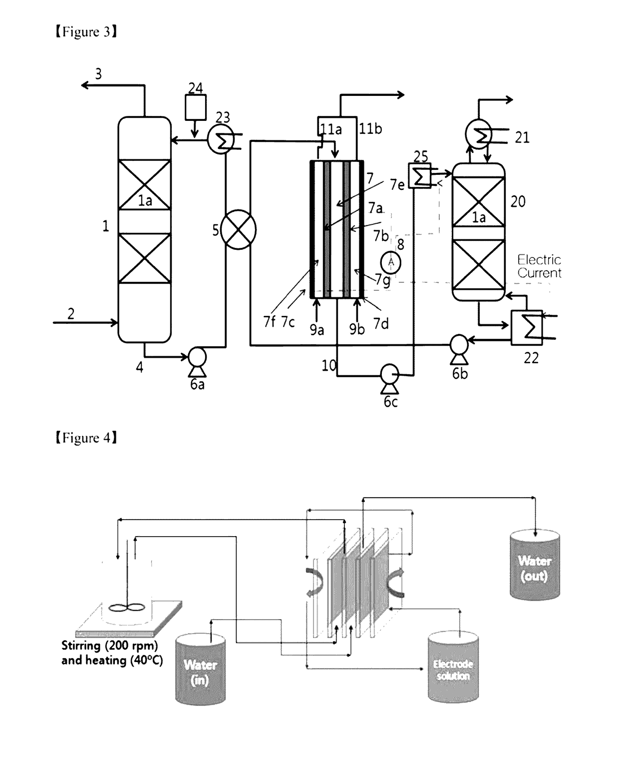
[0106]In Example 1 of the present invention, as shown in a schematic diagram of a carbon dioxide absorption device capable of producing electricity in FIG. 4, a carbon dioxide absorbing device that is capable of producing electricity and is configured of five each of a cation exchange membrane (commercially available from Fumatech and Astom Corporation) and an anion exchange membrane (commercially available from Fumatech) between rectangular positive and negative electrodes (graphite electrodes) having a micro-flow path, a spacer, an absorption solution (KIERSOL: a mixture including 15% by weight of K2CO3, 10% by weight of 2-methylpiperazine, and water), a vessel with a stirrer through which carbon dioxide is reacted (10 mL / min, 200 rpm, 40° C.), a vessel for inputting freshwater (10 mL / min) and a vessel for circulating an electrolyte (a mixed solution of ferrocyanide and NaCl: Fe(CN)63− / 4−50 mM, 20 mL / min), was manufactured.

[0107]A total generated energy, the voltage, and the maxim...

example 2

[0109]Referring to FIG. 7, the experimental results of the carbon dioxide capturing apparatus capable of producing electricity were able to be confirmed. An experiment was performed using a selective ion exchange membrane (0.0071 m2) commercially available from Fumatech, a graphite electrode, five stacks of exchange membranes, a spacer (0.2 mm), saline water (10 mL / min), freshwater (5 mL / min), and an electrolyte (10 mL / min) were used.

[0110]It was revealed that a KIERSOL solution was measured to have a voltage of 0.3 to 0.4 V and a power density value of 0.3 to 0.4 W / m2. Also, it was revealed that a KIERSOL solution having absorbed carbon dioxide was measured to have a voltage of 0.5 V and a power density value of 0.7 to 0.8 W / m2.


PUM


Abstract

A carbon dioxide capturing apparatus and process uses a self-generating power means that uses carbon dioxide in combustion exhaust gas through the convergence of a carbon dioxide absorption tower. The capturing apparatus and process also relies on ionic generator associated technology using a concentration difference between seawater and freshwater. The capturing apparatus and process result in increased production efficiency for electric energy and reduced costs for a carbon dioxide capturing process by increasing a concentration difference using an absorbent liquid for absorbing carbon dioxide and, at the same time, electricity is obtained through carbon dioxide which is a greenhouse gas.

Description

TECHNICAL FIELD[0001]The present invention relates to an apparatus and process for capturing carbon dioxide from among combustion exhaust gases. More particularly, the present invention relates to an apparatus and process for producing electricity and capturing carbon dioxide with a high degree of efficiency by utilizing carbon dioxide in combustion exhaust gases as a result of applying converging technologies associated with a carbon dioxide absorption tower, a regeneration tower and an electricity-generating device using ion.BACKGROUND ART[0002]Carbon dioxide, which is the most abundant of the six major greenhouse gases causing global warming, is an acidic gas, and there is a restriction on the number of facilities permitted to discharge carbon dioxide in large quantities. Carbon dioxide is generally generated as a result of burning fossil fuels and thus is mainly generated in industrial processes in which energy is generated or consumed in large quantities.[0003]According to a st...

Claims


Application Information

Patent Timeline
Patent Type & Authority Applications(United States)
IPC IPC(8): B01D53/14B01D53/62B01D53/96
CPCB01D53/1425B01D53/62B01D53/965B01D53/1475Y02A50/20Y02C20/40B01D53/14B01D53/96
Inventor YOON, YEO ILKIM, HAN KINAM, SUNG CHANKIM, CHAN SOOPARK, SUNG YEOULJEONG, NAM JOKIM, YOUNG EUN
Owner KOREA INST OF ENERGY RES
Why Eureka
Try Eureka