Refrigeration cycle device
a technology of refrigerating cycle and apparatus, which is applied in the direction of refrigeration components, compression machines with several condensers, light and heating apparatus, etc., can solve the problems of high cost and achieve the effect of suppressing disproportionation and high composition ratio
- Summary
- Abstract
- Description
- Claims
- Application Information
AI Technical Summary
Benefits of technology
Problems solved by technology
Method used
Image
Examples
first embodiment
[0021]The configuration of a refrigeration cycle apparatus will be first discussed below.
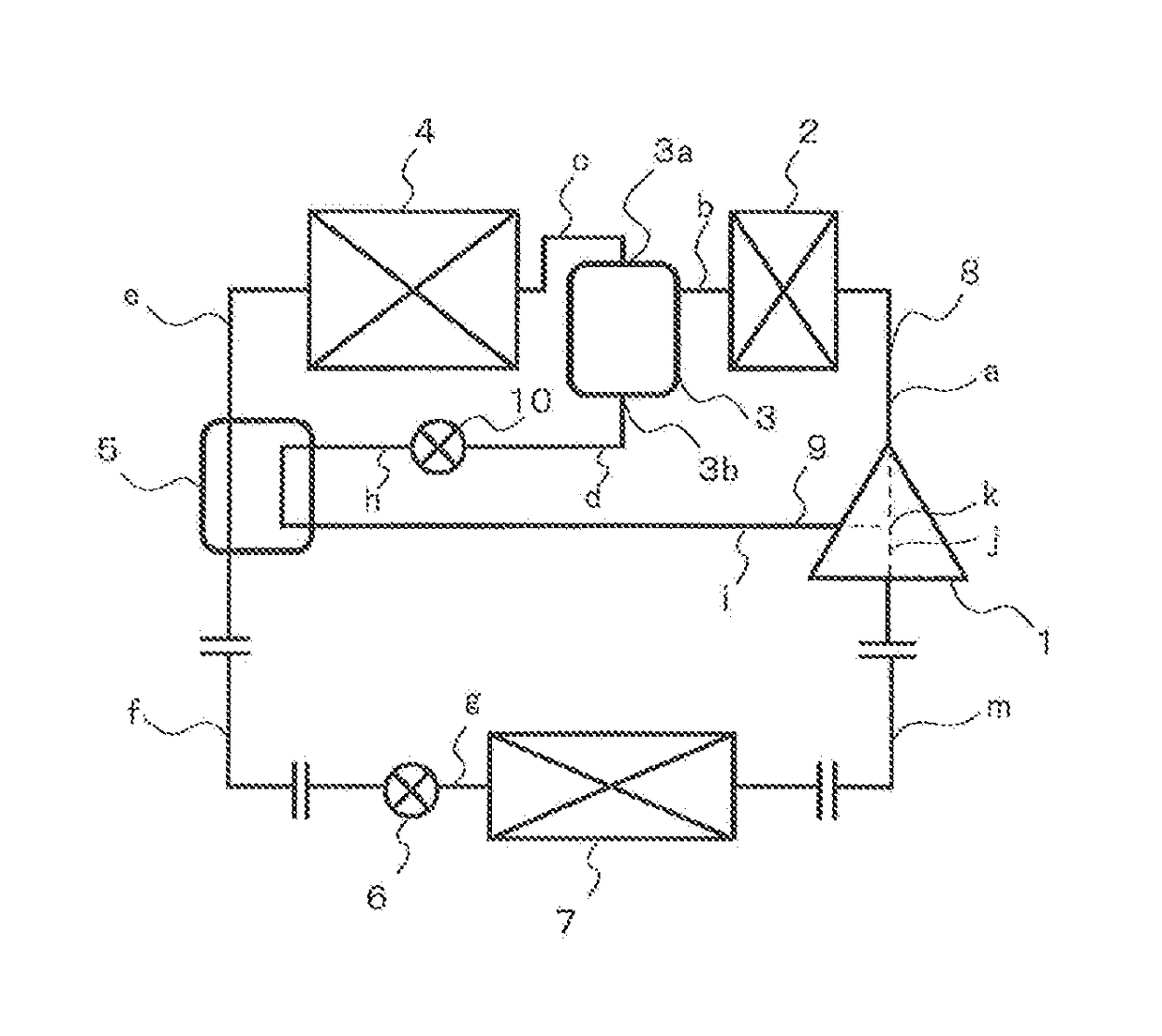
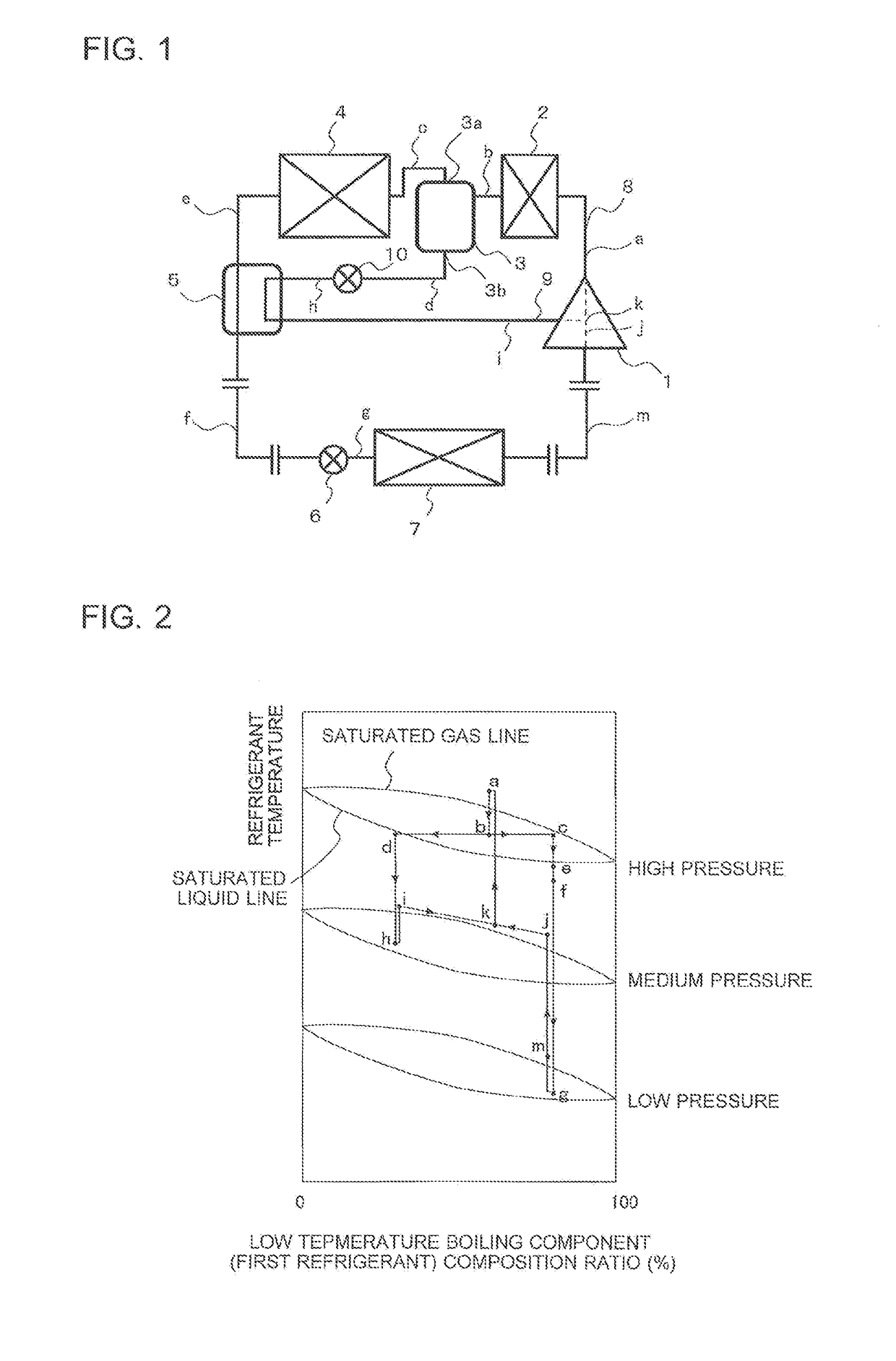
[0022]FIG. 1 is a schematic diagram of the refrigeration cycle apparatus according to a first embodiment.
[0023]As shown in FIG. 1, the refrigeration cycle apparatus according to the first embodiment has a refrigeration cycle including a compressor 1, a first condenser 2, a liquid separator 3, a second condenser 4, a refrigerant heat exchanger 5, a first expansion valve 6, and an evaporator 7 that are sequentially connected via a refrigerant pipe serving as a main passage 8. A gas outlet 3a provided to an upper part of the liquid separator 3 is connected to the second condenser 4.
[0024]A liquid outlet 3b provided to a lower part of the liquid separator 3 is connected to the compressor 1 via a bypass 9. The bypass 9 is connected to an intermediate pressure part (an intermediate pressure between a high pressure and a low pressure, will be referred to as a medium pressure) in a compression chamber. ...
second embodiment
[0055]The configuration of a refrigeration cycle apparatus will be first described below.
[0056]The working refrigerant of the refrigeration cycle apparatus according to a second embodiment is identical to that of the first embodiment and thus differences in configuration will be discussed below.
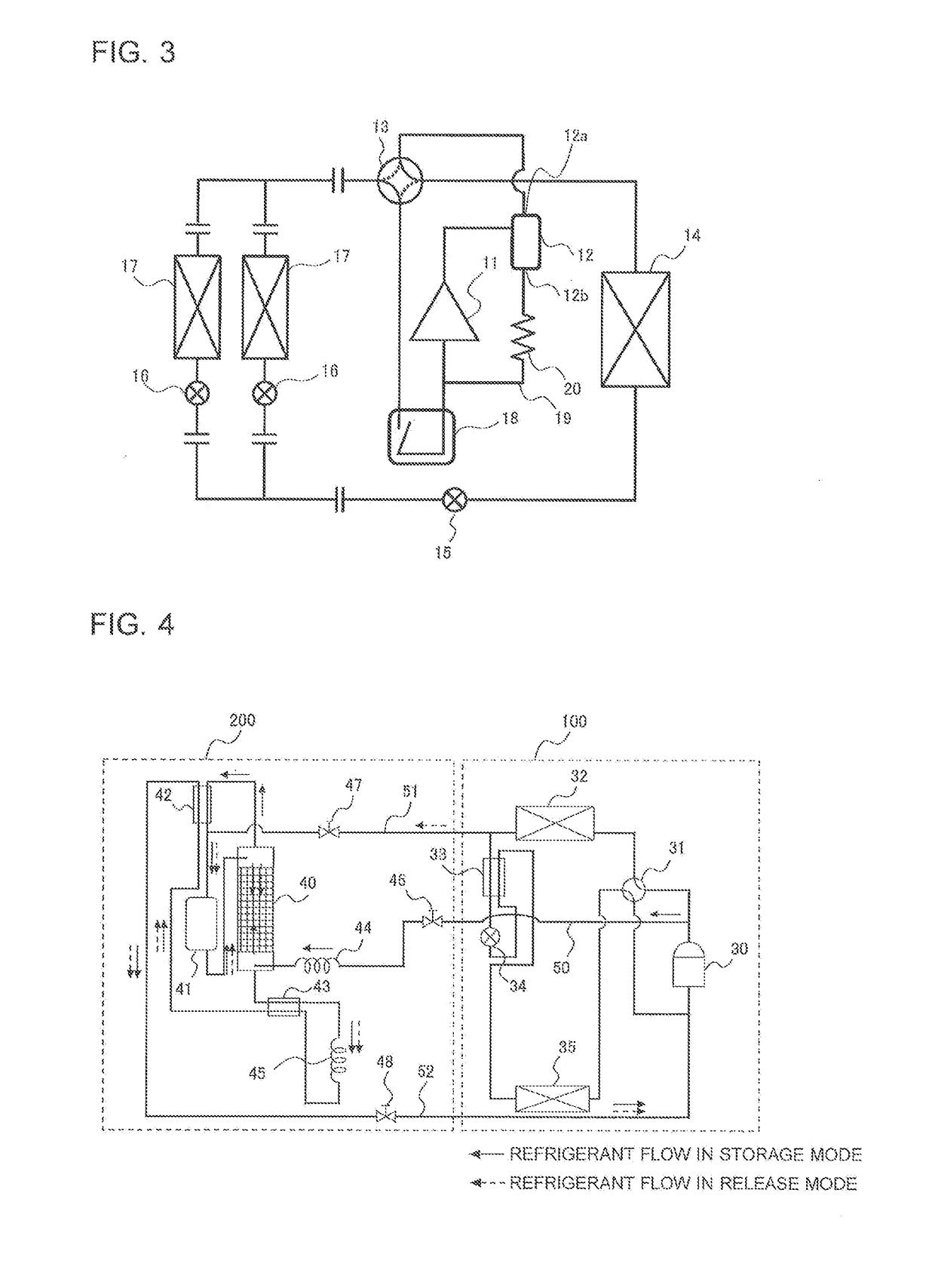
[0057]FIG. 3 is a schematic diagram of the refrigeration cycle apparatus according to the second embodiment.
[0058]The refrigeration cycle apparatus according to the second embodiment has a refrigeration cycle including a compressor 11, an oil separator 12, a four-way valve 13, an exterior heat exchanger 14, an exterior expansion valve 15, interior expansion valves 16, interior heat exchangers 17, the four-way valve 13, and an accumulator 18 that are sequentially connected. The interior expansion valves 16 and the interior heat exchangers 17 are connected in parallel. A gas outlet 12a of the oil separator 12 is connected to the four-way valve 13. An oil return port 12b of the oil separator 12 ...
third embodiment
[0085]The configuration of a refrigeration cycle apparatus will be first described below.
[0086]The working refrigerant of the refrigeration cycle apparatus according to a third embodiment is identical to that of the first embodiment and thus differences in configuration will be discussed below.
[0087]FIG. 4 is a schematic diagram of the refrigeration cycle apparatus according to the third embodiment.
[0088]As shown in FIG. 4, the refrigeration cycle apparatus according to the third embodiment includes a compressor 30, a four-way valve 31, a user-side heat exchanger 32, a subcooler 33, an expansion valve 34 acting as a first decompression device, and a heat-source-side heat exchanger 35. These components are sequentially connected via refrigerant pipes and are stored in a refrigeration cycle unit 100.
[0089]A component separation circuit includes a refrigerant rectifier 40 acting as a component separating unit, a refrigerant reservoir 41 for retaining refrigerant, a first cooler 42, a s...
PUM
 Abstract
Description
Claims
Application Information
 - R&D
- Intellectual Property
- Life Sciences
- Materials
- Tech Scout
- Unparalleled Data Quality
- Higher Quality Content
- 60% Fewer Hallucinations
Browse by: Latest US Patents, China's latest patents, Technical Efficacy Thesaurus, Application Domain, Technology Topic, Popular Technical Reports.
© 2025 PatSnap. All rights reserved.Legal|Privacy policy|Modern Slavery Act Transparency Statement|Sitemap|About US| Contact US: help@patsnap.com


