Fuel cell stack

a fuel cell and stack technology, applied in the field can solve the problems of delayed temperature rise of end cells and limited output of fuel cell stacks, and achieve the effects of improving the temperature of the low temperature part, improving the uniformity of unit cells, and improving cell voltage due to the temperature deviation between cells

Active Publication Date: 2017-03-23
HYUNDAI MOTOR CO LTD
View PDF0 Cites 0 Cited by
  • Summary
  • Abstract
  • Description
  • Claims
  • Application Information

AI Technical Summary

Benefits of technology

The present invention provides a fuel cell stack that has a simplified structure and improved heat distribution and temperature uniformity. This is achieved by installing planar heat transfer members at the outermost sides of the unit cells, which allows for rapid heat transfer between high and low temperature parts. This reduces temperature deviation between cells and improves fuel cell output and durability, while also reducing manufacturing costs compared to traditional fuel cell stacks. Additionally, the use of planar heat transfer members at the opposite ends of the stack simplifies the structure and improves heat distribution without adding complexity.

Problems solved by technology

A temperature deviation between the cells of the fuel cell stack occurs mainly during the cold-starting or the cold-driving of the fuel cell stack, and is caused due to the heat generated in the end cell being absorbed by components (e.g., the end plate and the current collector) having a substantially large heat capacity around the end cell and thus, a temperature rise of the end cell is delayed.
Due to a low temperature of the end cell, reaction gas may be excessively humidified to cause flooding at the end cell.
Accordingly, the reaction gas is supplied insufficiently at the end cell for a voltage of the cell to decrease, thus an output of the fuel cell stack may be limited.

Method used


Image

  • Fuel cell stack
  • Fuel cell stack
  • Fuel cell stack

Examples


Embodiment Construction

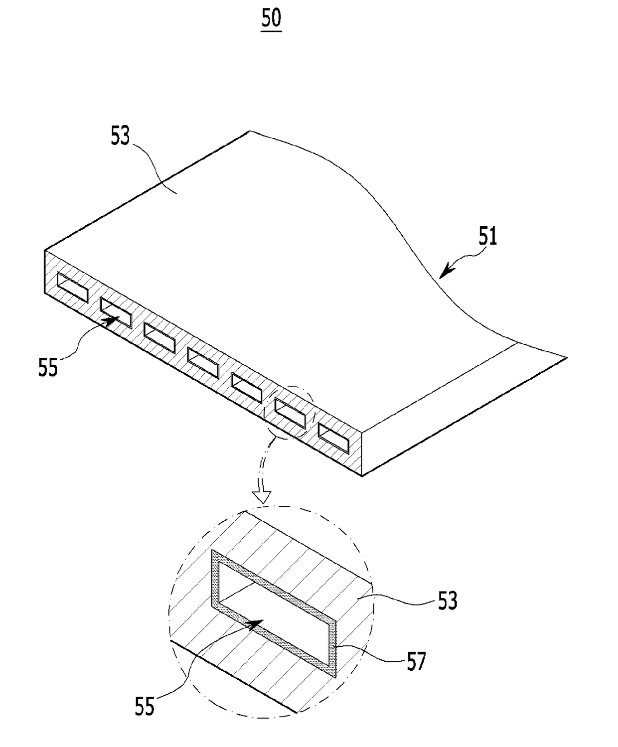
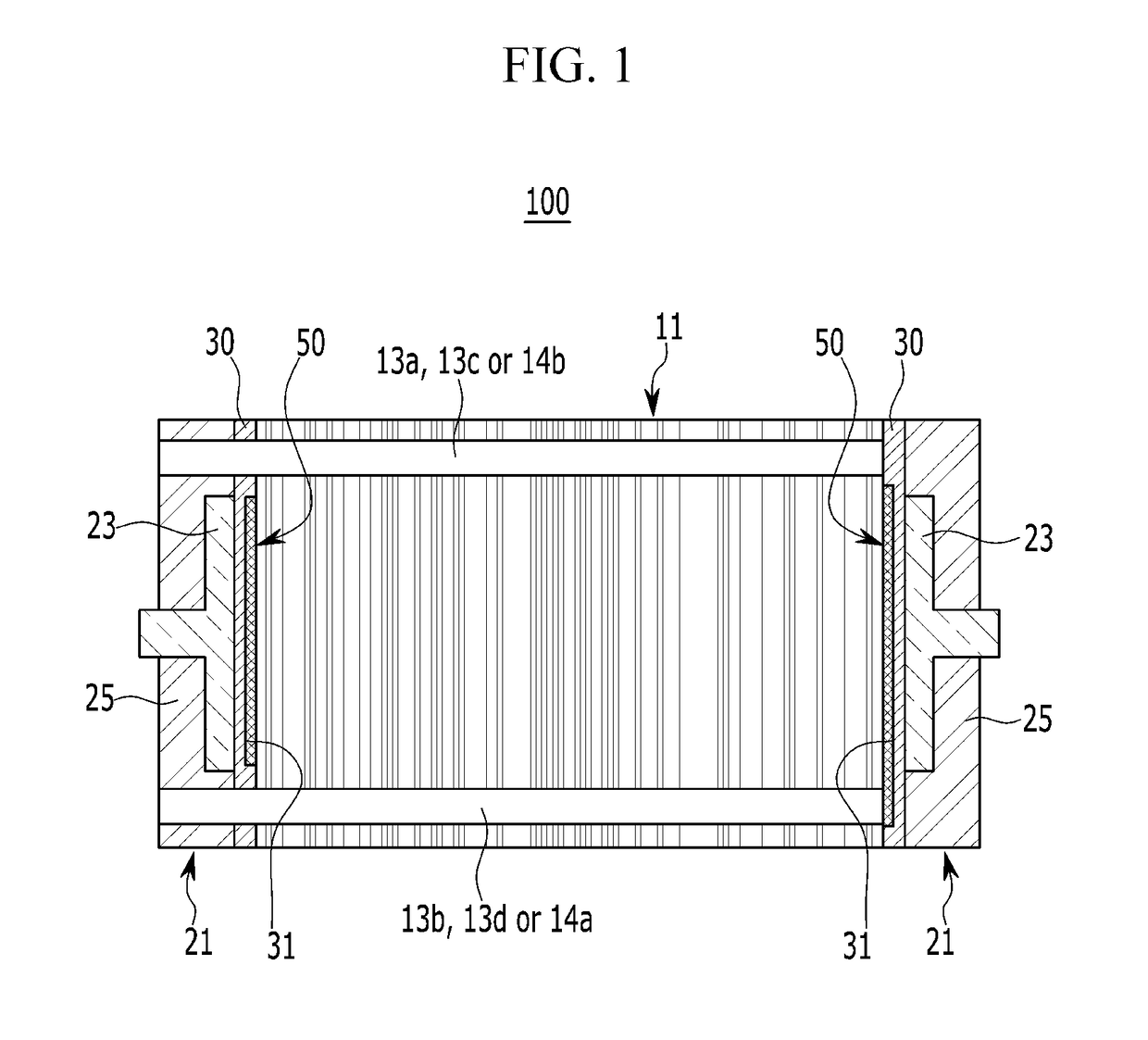
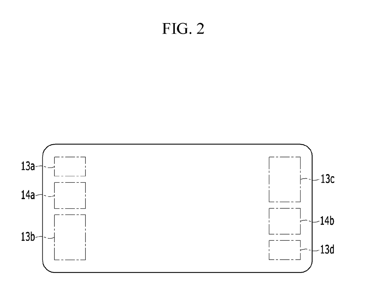
[0043]Hereinafter, the present invention will be described more fully with reference to the accompanying drawings, in which exemplary embodiments of the invention are shown. As those skilled in the art would realize, the described exemplary embodiments may be modified in various different ways, all without departing from the spirit or scope of the present invention. Parts which are not related with the description are omitted for clearly describing the exemplary embodiment of the present invention, and like reference numerals refer to like or similar elements throughout the specification.

[0044]It is understood that the term “vehicle” or “vehicular” or other similar term as used herein is inclusive of motor vehicles in general such as passenger automobiles including sports utility vehicles (SUV), buses, trucks, various commercial vehicles, watercraft including a variety of boats and ships, aircraft, and the like, and includes hybrid vehicles, electric vehicles, plug-in hybrid electri...


PUM

PropertyMeasurementUnit
temperatureaaaaaaaaaa
lengthaaaaaaaaaa
widthaaaaaaaaaa

Abstract

A fuel cell stack is provided and includes a plurality of unit cells in which manifolds are provided and an end structural body that includes a current collector and an end plate. The end structural body is disposed at each of outermost sides of the unit cells. Additionally, a heat transfer member is disposed between the end structural body and the outermost side of the unit cell and contacts the outermost side of the unit cell in a planar direction.

Description

CROSS-REFERENCE TO RELATED APPLICATION[0001]This application claims priority to and the benefit of Korean Patent Application No. 10-2015-0134956 filed in the Korean Intellectual Property Office on Sep. 23, 2015, the entire contents of which are incorporated herein by reference.BACKGROUND[0002](a) Field of the Invention[0003]The present invention relates to a fuel cell stack, and more particularly, to a fuel cell stack in which that temperature deviation between cells is reduced.[0004](b) Description of the Related Art[0005]A fuel cell stack is an electric power generating device that generates electrical energy through an electrochemical reaction between hydrogen and oxygen in respective fuel cells thereof, and is applied to a fuel cell vehicle, etc. Further, the fuel cell stack is a fuel cell assembly in which fuel cells are arranged sequentially. The fuel cell is a unit cell in which a separator is respectively disposed at opposite sides of a membrane-electrode assembly (MEA) with...

Claims


Application Information

Patent Timeline
Patent Type & Authority Applications(United States)
IPC IPC(8): H01M8/04007H01M8/04014H01M8/2465H01M8/04029
CPCH01M8/04067H01M8/04029H01M2250/20H01M8/2465H01M8/04014H01M8/24H01M8/241H01M8/2483Y02T90/40Y02E60/50
Inventor KWON, HYUCK ROULKIM, HYUNYOOKIM, JUHAN
Owner HYUNDAI MOTOR CO LTD
Why Eureka
Try Eureka