Methods and systems for cone-beam computed tomography

Active Publication Date: 2017-03-30
GENERAL ELECTRIC CO
View PDF35 Cites 22 Cited by
  • Summary
  • Abstract
  • Description
  • Claims
  • Application Information

AI Technical Summary

Benefits of technology

[0005]In one embodiment, a method for an imaging apparatus comprises calculating a likelihood of a collision between the imaging apparatus and a subject based on a model of the subject, performing a scan of the subject responsive t

Problems solved by technology

Such CT system configurations typically have a small field of view and thus can only image a small portion of an object during a single scan.
However, it is possible that the detector and/or the source may collide with the patient because the patient is now positioned closer to the trajectories of the detector and the source.
In some instances, repositioning the patient may lead to the

Method used


Image

  • Methods and systems for cone-beam computed tomography
  • Methods and systems for cone-beam computed tomography
  • Methods and systems for cone-beam computed tomography

Examples


Embodiment Construction

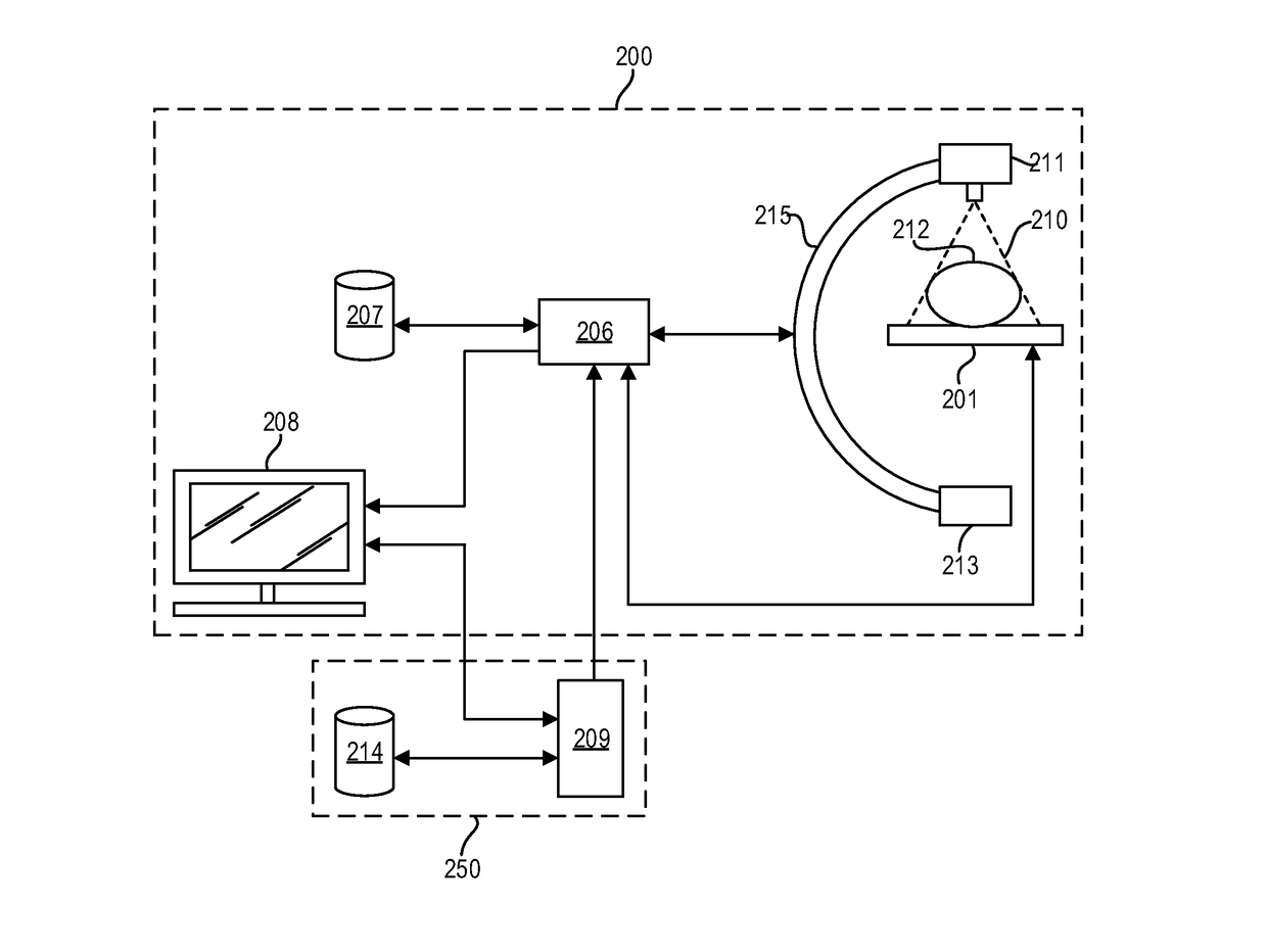
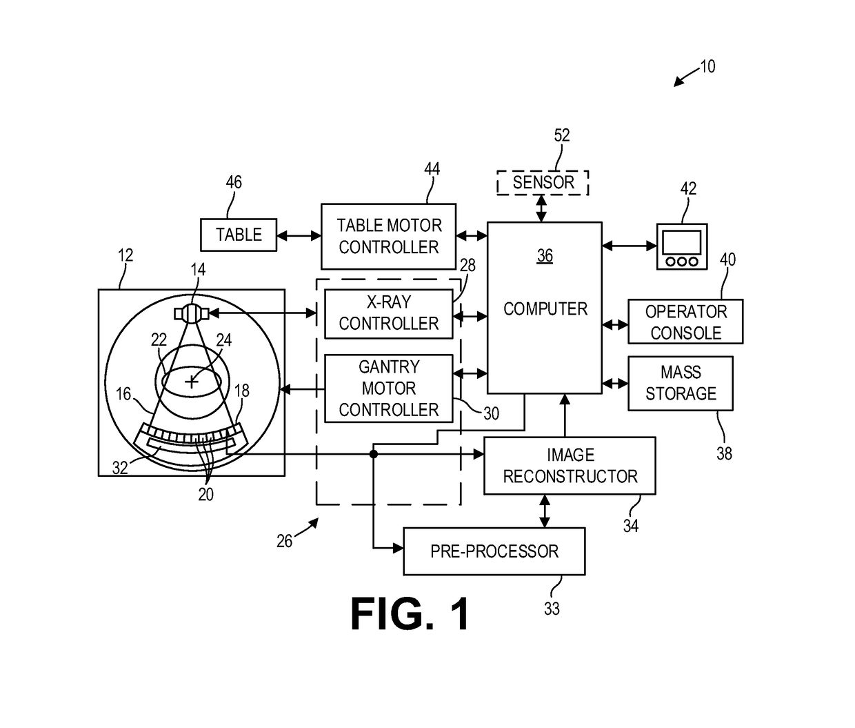
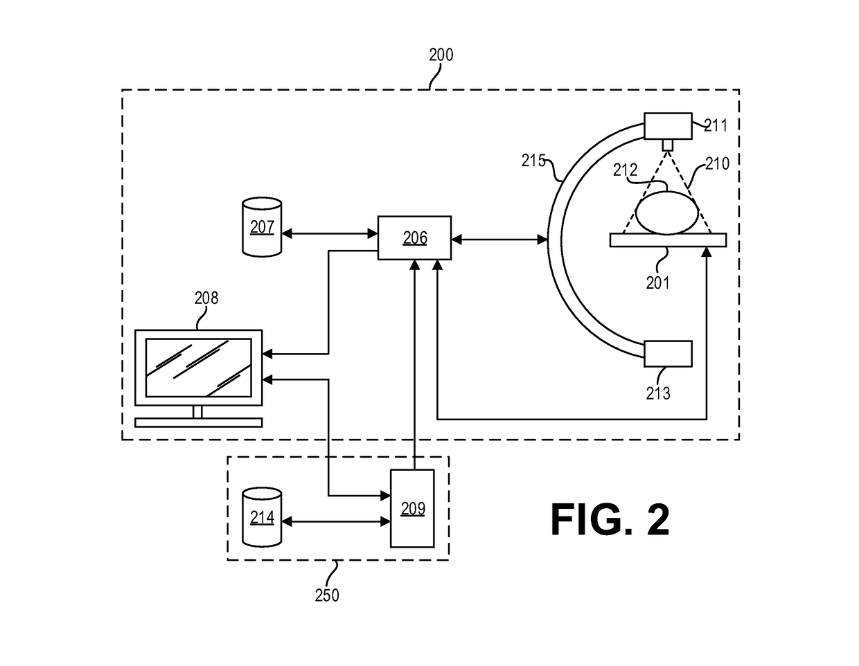
[0015]The following description relates to various embodiments of medical imaging systems. In particular, methods and systems are provided for collision avoidance in a computed tomography (CT) imaging system. An example of a CT imaging system that may be used to acquire images processed in accordance with the present techniques is provided in FIG. 1. Though a CT system is described by way of example, it should be understood that the present techniques may also be useful when applied to images acquired using other imaging modalities, such as tomosynthesis, MRI, PET, SPECT, C-arm angiography, mammography ultrasound, and so forth. The present discussion of a CT imaging modality is provided merely as an example of one suitable imaging modality. For example, a CT system in a C-arm configuration, such as the system depicted in FIG. 2, includes a source and a detector mounted opposite to each other on the ends of a substantially C-shaped or semi-circular gantry, or C-arm, thereby defining ...


PUM


Abstract

Various methods and systems are provided for collision avoidance in cone-beam computed tomography (CT) systems. In one embodiment, a method for an imaging apparatus comprises calculating a likelihood of a collision between the imaging apparatus and a subject and/or its support based on a model of the subject, performing a scan of the subject responsive to the likelihood below a threshold, and not performing the scan otherwise. In this way, collisions between the patient and the imaging apparatus can be avoided.

Description

FIELD[0001]Embodiments of the subject matter disclosed herein relate to non-invasive imaging, and more particularly, to collision avoidance in cone beam computed tomography imaging systems.BACKGROUND[0002]In cone-beam computed tomography (CT) systems, an x-ray source and an x-ray detector are generally mounted on opposing ends of a substantially C-shaped gantry such that x-rays emitted by the source in a cone-shaped beam are incident on and detectable by the x-ray detector. The source and the detector are positioned such that when an object (e.g., a human extremity) is interposed there between and is irradiated with x-rays, the detector produces data representative of characteristics of the interposed object. The data produced is typically displayed on a monitor or electronically stored.[0003]The C-arm gantry defines an axis of rotation about which the source and detector are rotatable. By positioning this axis of rotation at or near an object, and by rotating the source and detecto...

Claims


Application Information

Patent Timeline
IPC IPC(8): A61B6/10A61B6/03A61B6/00
CPCA61B6/102A61B6/4441A61B6/032A61B6/4085A61B6/488A61B6/542A61B6/545A61B6/547A61B6/035A61B6/10A61B6/4435
Inventor MC CARTHY, THOMASTROUSSET, YVES LUCIEN
Owner GENERAL ELECTRIC CO
Why Eureka
Try Eureka