
Rim for a wheel

a technology of rims and wheels, applied in the field of wheels, can solve the problems of tire deflation, structural integrity, and recent designs can have certain drawbacks, and achieve the effect of improving stiffness and impact resistan

Active Publication Date: 2017-03-30
DYMAG GRP LTD
View PDF5 Cites 11 Cited by
  • Summary
  • Abstract
  • Description
  • Claims
  • Application Information

AI Technical Summary

Benefits of technology

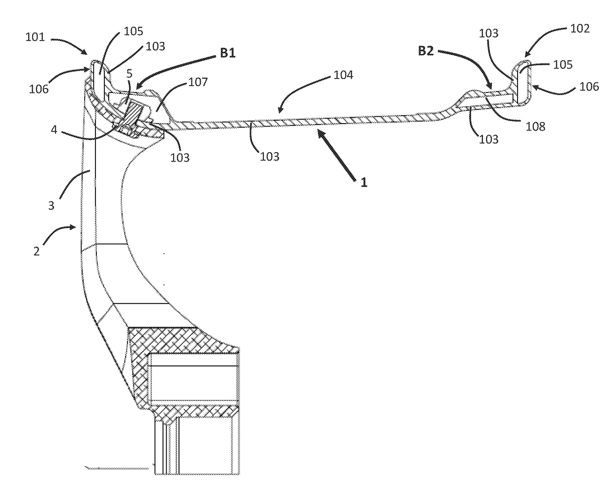
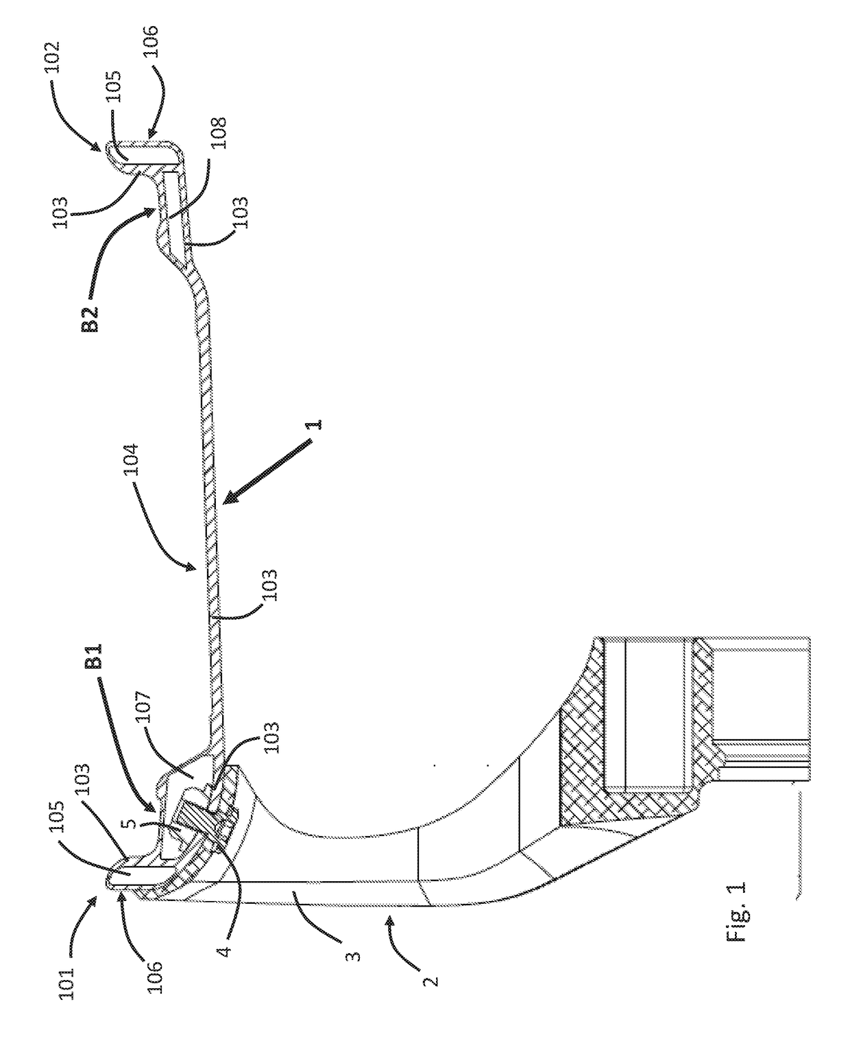
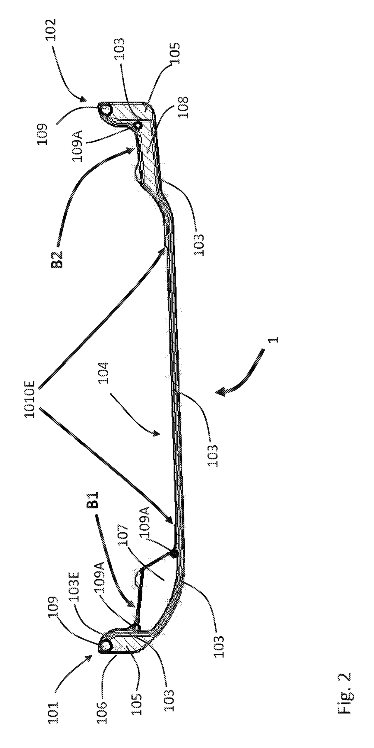
The present invention relates to a new design for the rim of a composite wheel that reduces the risk of damage from sudden and high loads. The rim is made of a lightweight and strong material that allows its use in high-performance situations and is easy to detect and mitigate any damage. The invention also includes the use of an engineered 3D fibre layered material to replace foam, which improves stiffness and impact resistance. The new design can be used in Hybrid and MonoBloc wheels, and improves manufacturing repeatability.

Problems solved by technology

However, even recent designs can have certain drawbacks.
For example, some wheels that experience very high and / or sudden axial or radial loads or impacts can experience a loss in the structural integrity of the wheel, which can lead to tire deflation and / or a loss of control of a vehicle.
Additionally structural damage to a rim can mean the entire rim needs to be replaced, for safety reasons, owing to the difficulty of accurate damage assessment and the lack of easily replaceable elements, rather than simply being repaired.
Sometimes, damage can go undetected on rims, which can be a safety problem if the wheels are used on, and then fail on, a vehicle.

Method used


Image

  • Rim for a wheel
  • Rim for a wheel
  • Rim for a wheel

Examples


examples

[0152]A radial load test was carried out on two different types of wheel: (i) a wheel comprising a rim according to the disclosure (denoted Mk2 design below) and (ii) a reference wheel (denoted Mk1 design below). A schematic illustration of the test equipment is shown in FIG. 9. The test comprises a driven drum 901 on which the test wheel is mounted under a radial load, as shown in FIG. 9; this type of test is normally referred to as a radial fatigue test. In this Figure, the driven drum is denoted 901, the wheel being tested denoted 2, the rim of the wheel denoted 1, the tyre on the wheel denoted 902, the spokes of the wheel denoted 3 and the radial load by an arrow 903. The number of wheel revolutions before failure, defined at the point of tyre deflation or wheel breaking, is recorded. The described test was undertaken in accordance with SAE J328. The test described herein was undertaken using a wheel assembly including a carbon fibre rim (in accordance with the present disclosur...

example embodiment 2

according to Example Embodiment 1, wherein a protective insert is disposed between an outer face of the first flange and the primary structural component and at least a portion of the first bead seat is spaced apart from the primary structural component.

example embodiment 3

according to Example Embodiment 1 or Example Embodiment 2, wherein the rim is for a wheel suitable for a four-wheeled vehicle and first flange is an outboard flange.


PUM

PropertyMeasurementUnit
Coloraaaaaaaaaa
Circumferenceaaaaaaaaaa
Stiffnessaaaaaaaaaa

Abstract

Herein is described a non-metallic rim for a wheel, the rim comprising:a barrel having first and second flanges extending radially outward from opposing edges of the barrel, and the barrel comprising a first bead seat and a second bead seat arranged axially inwardly, respectively, of the first and second flanges,whereina primary structural component extends at least through the first flange and the barrel, the primary structural component being capable of bearing the majority of the radial and / or lateral load that, in use, would be borne by the rima protective insert is disposed between an outer face of the first flange and the primary structural component and / orat least a portion of the first bead seat is spaced apart from the primary structural component andthe primary structural component, bead seat and, if present, the protective insert are bound by a polymer matrix.

Description

CROSS REFERENCE TO RELATED APPLICATIONS[0001]This application is a continuation of and claims priority to co-pending PCT application number PCT / GB2016 / 052533, filed 16 Aug. 2016; which claims priority to GB1610361.6, filed 14 Jun. 2016. This application also claims priority to DE 20 2016 105 179.7, filed 16 Sep. 2016. All of which are hereby incorporated by reference in their entireties for any and all non-limiting purposes.FIELD OF INVENTION[0002]This application relates to wheels, particularly wheels having a non-metallic rim, such as a rim comprising fibre composite and / or plastic materials. The rims and wheels described herein may, for example, be for use with motorised and non-motorised vehicles such as automobiles, motorcycles, bicycles and aircraft etc.BACKGROUND[0003]Wheels made from composite materials, such as fibre-reinforced plastics, have made major advances in recent years. However, even recent designs can have certain drawbacks. For example, some wheels that experienc...

Claims


Application Information

Patent Timeline
IPC IPC(8): B60B5/02B60B21/10B60B21/12B60B21/02
CPCB60B5/02B60B2900/212B60B21/102B60B21/104B60B21/12B60B2360/36B60B2360/341B60B2360/3412B60B2360/3418B60B2360/3416B60B2360/344B60B3/001B60B2900/572B60B2360/362B60B2310/318B60B21/023B60B21/026B60B21/028B60B21/04B60B2310/321B60B2310/52B60B2310/80B60B2900/311B60B2900/321B60B2900/3312B60B2310/323B29C70/865B60B5/00
Inventor WALLS-BRUCK, MARCUSWILSON, MICHAEL JOHNSHELLEY, CHRISTOPHER
Owner DYMAG GRP LTD
Learn More