
Hybrid vehicle control apparatus

Active Publication Date: 2017-03-30
TOYOTA JIDOSHA KK
View PDF3 Cites 26 Cited by
  • Summary
  • Abstract
  • Description
  • Claims
  • Application Information

AI Technical Summary

Benefits of technology

This patent describes a control system for hybrid vehicles that improves fuel efficiency and reduces battery deterioration by extracting target-downhill sections in the vehicle's travel route. The system takes into account the vehicle's speed and reduces the remaining battery capacity in the target-downhill section to execute a downhill control operation. The system also increases the height difference threshold for extracting target-downhill sections on expressways to ensure reliability. Overall, the system improves fuel efficiency and reduces battery deterioration in a more targeted manner.

Problems solved by technology

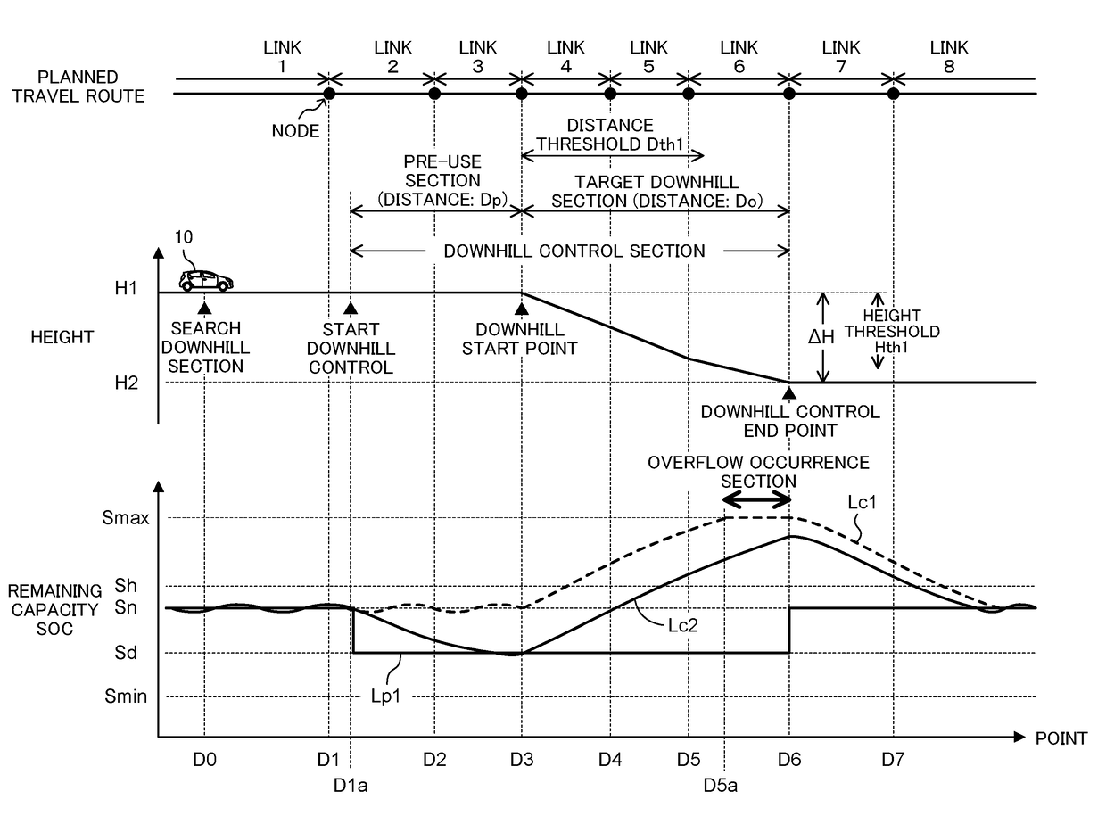
However, when the downhill section is long, the remaining capacity SOC reaches the remaining capacity upper limit, which makes it impossible to increase the remaining capacity SOC further.
Therefore, when the conventional apparatus extracts a “downhill section in which the vehicle travels at high vehicle speed” as a target-downhill-section because the height difference of that downhill section is greater than the above-mentioned height difference threshold and executes the downhill control, there is very likely to arise a situation in which the remaining capacity SOC does not increase sufficiently before the vehicle ends the travel in that downhill section.
As a result, the remaining capacity SOC may reach the remaining capacity lower limit, and forced charging (charging the storage battery by the output of the engine) may occur.
However, the conventional apparatus does not execute the downhill control for such a downhill section because the height difference is smaller than the height difference threshold.
Accordingly, the conventional apparatus may fail to yield the fuel efficiency improving effect to a sufficient degree.
In addition, the apparatus can restrain occurrence of a phenomenon that since the remaining capacity SOC does not increase sufficiently during the travel in the target-downhill-section, charging and discharging are repeated in a state in which the remaining capacity SOC is low, whereby deterioration of the storage battery accelerates.

Method used


Image

  • Hybrid vehicle control apparatus
  • Hybrid vehicle control apparatus
  • Hybrid vehicle control apparatus

Examples


first embodiment

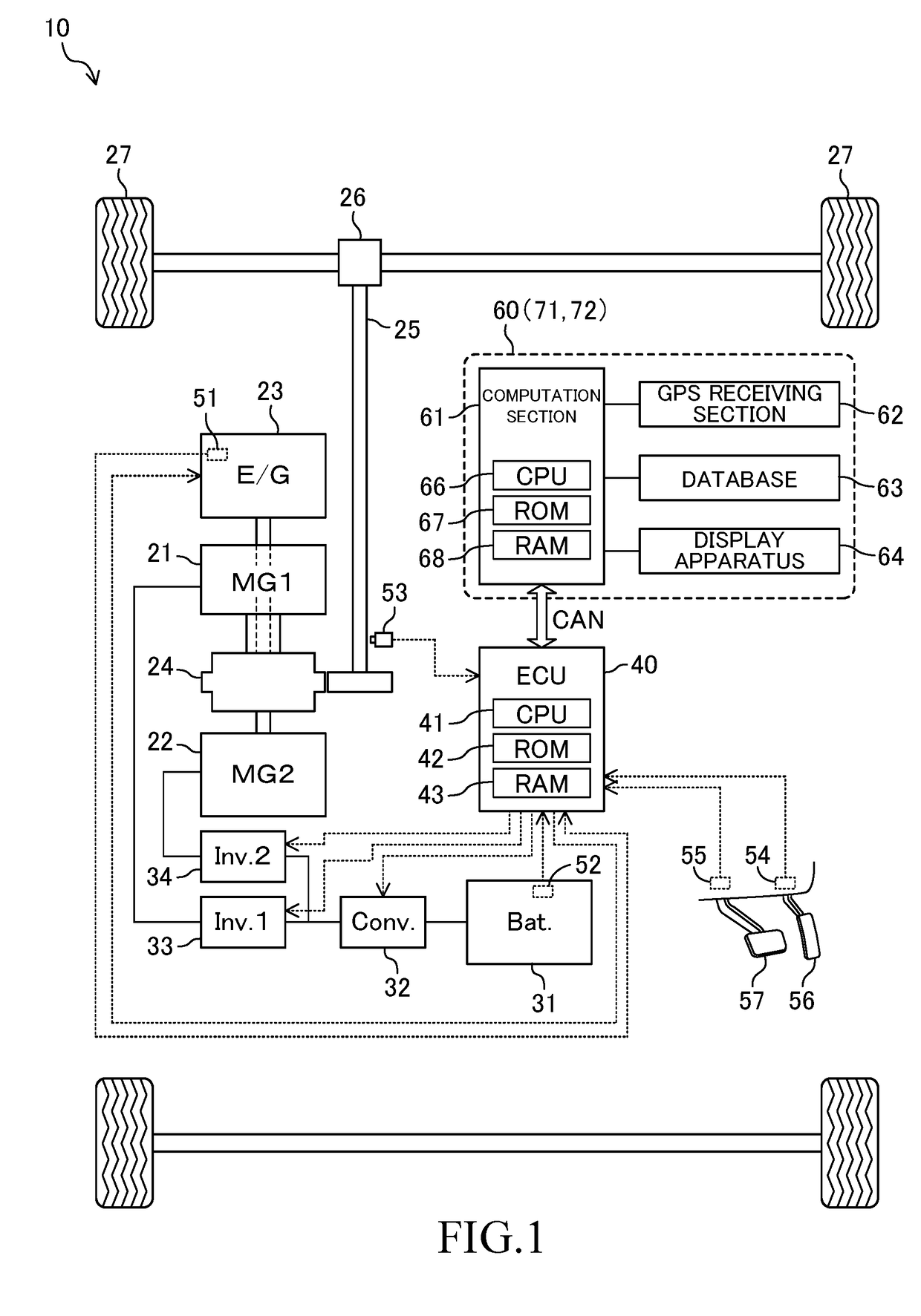
[0049]A hybrid vehicle control apparatus according to a first embodiment (hereinafter also referred to as the “first control apparatus”) is applied to a vehicle 10 as shown in FIG. 1. The vehicle 10 includes a first motor 21, a second motor 22, and an engine 23. Namely, the vehicle 10 is a hybrid vehicle.

[0050]The vehicle 10 further includes a power split mechanism 24, a storage battery 31, a step-up converter 32, a first inverter 33, a second inverter 34, an ECU (Electronic Control Unit) 40, and a travel assisting apparatus 60. The ECU 40 and the travel assisting apparatus 60 constitute the first control apparatus.

[0051]Each of the first motor 21 and the second motor 22 is a three-phase synchronous generator-motor which functions as a generator and a motor. The first motor 21 is mainly used as a generator. The first motor 21 also cranks the engine 23 when the engine 23 is to be started. The second motor 22 is mainly used as a motor and can generate vehicle drive force (torque for c...

second embodiment

[0242]Next, a hybrid vehicle control apparatus according to a second embodiment (hereinafter also referred to as the “second control apparatus”) will be described. The first control apparatus extracts a target-downhill-section on the basis of the road type (either of an ordinary road and an expressway) of each of links which constitute the planned travel route. The second control apparatus differs from the first control apparatus only in the point that the second control apparatus extracts a target-downhill-section on the basis of the estimated vehicle speed Ve at the time when the vehicle 10 travels through each of links which constitute a section to be judged. Accordingly, this difference will be mainly described below.

[0243]The map database stored in the database 63 of a travel assisting apparatus 71 according to the second control apparatus contains estimated vehicle speed Ve which is the estimated average of the vehicle speed Vs at the time when the vehicle 10 travels through e...

third embodiment

[0267]Next, a hybrid vehicle control apparatus according to a third embodiment (hereinafter also referred to as the “third control apparatus”) will be described. The second control apparatus selectively uses different height difference thresholds (the height difference threshold Hth1 and the height difference threshold Hth2) depending on the result of the judgment as to whether or not the estimated vehicle speed Ve of each of the links constituting the section to be judged is less than the speed threshold Vth (namely, whether each link is a low speed section or a high speed section). The third control apparatus differs from the second control apparatus only in the point that the third control apparatus estimates the section average speed Vd of the section to be judged on the basis of the estimated vehicle speed Ve of each of the links constituting the section to be judged and determines the height difference threshold Hthv in accordance with the section average speed Vd. Accordingly...


PUM


Abstract

A control apparatus for a hybrid vehicle including an internal combustion engine, a motor, and a storage battery and which charges the storage battery with electric power generated as a result of regenerative braking and electric power generated by using an output of the engine. When a planned travel route includes a downhill section whose height difference is greater than a predetermined height difference threshold, the controller executes a downhill control operation that decreases the target remaining capacity of the storage battery. The controller increases the height difference threshold as the estimated average speed of the vehicle during travel in the downhill section increases, to thereby restrain the execution of the downhill control for a downhill section in which an increase in the remaining capacity is not expected due to a large air resistance acting on the vehicle.

Description

BACKGROUND[0001]1. Technical Field[0002]The present disclosure relates to a control apparatus for a hybrid vehicle which includes both an internal combustion engine and a motor as drive sources of the vehicle.[0003]2. Description of Related Art[0004]There has been known a hybrid vehicle (hereinafter also referred to as the “vehicle” for simplicity) which includes both an internal combustion engine (hereinafter also referred to as the “engine” for simplicity) and a motor as drive sources of the vehicle. Such a vehicle includes a storage battery which supplies electric power to the motor and which is charged by output of the engine.[0005]In addition, when rotation of a wheel axle is transmitted to the motor, the motor generates electric power (i.e., an electric generator generates electric power), and the storage battery is charged by the electric power as well. Namely, the kinetic energy of the vehicle is converted to electrical energy, and the electrical energy is collected by the s...

Claims


Application Information

Patent Timeline
IPC IPC(8): B60W20/12B60L11/18B60W30/18B60L7/10B60W10/06B60W10/08B60L50/16
CPCB60W20/12B60W10/06B60W10/08B60W30/18127B60L7/10Y10S903/947B60W2550/145B60W2750/00B60W2720/103Y10S903/93B60L11/1862B60W10/26B60W2510/244B60W2710/244B60W2552/15B60W2552/25B60W2555/40B60K6/445B60W50/0097B60L58/13B60L58/15B60W2552/20B60W2556/50Y02T10/62Y02T10/70Y02T10/72B60W2754/00
Inventor OGAWA, YUKI
Owner TOYOTA JIDOSHA KK
Learn More