Human-Propellable Vehicle

a human-propelled vehicle and suspension technology, applied in the direction of vehicle mounted steering controls, resilient suspensions, pivoted suspension arms, etc., can solve the problems and reducing the workload of the damper and suspension components. , to achieve the effect of reducing the wheel to damper motion ratio, reducing workload, and increasing the lifespan of the damper and suspension components

Inactive Publication Date: 2017-03-30
GOWER COLLEGE SWANSEA
View PDF3 Cites 3 Cited by
  • Summary
  • Abstract
  • Description
  • Claims
  • Application Information

AI Technical Summary

Benefits of technology

[0006]In general terms, the new design replaces the suspension trailing arms on the rear of the vehicle with a double wishbone type set up, which significantly moves the pivot point of the rear suspension from being in front of the rider to being in line with the rider's torso. This type of set up reduces the wheel to damper motion ratio which in turn reduces the workload of and increases the lifespan of the damper and suspension components. This also allows for a more controlled vehicle dynamic resulting in more consistency over consecutive obstacles and reduces the potential for overturning the bicycle. By using a double wishbone set up at the rear of the bike instead of the more conventional trailing arm type set up it is possible to control weight transfer more efficiently.
[0007]While double wishbone suspension is well-known for motorised vehicles, it has not previously been possible to implement double wishbone suspension on a human-propelled vehicle while satisfying the vehicle dimension requirements referred to above. This is because a double wishbone suspension assembly extends laterally (sideways) from the body of a vehicle. In the case of a downhill bike the wishbones cannot be provided directly underneath the body because this would result in a higher seating position for the rider, thereby reducing stability. However, if the wishbones extend out from the side of the vehicle, the rear wheel track becomes too wide, with the result that the vehicle cannot operate on existing downhill trails, and cannot be comfortably self-propelled by manipulation of the rear wheels. However, the present invention, by providing a second coupling point for each wishbone which is closer to the rear of the chassis, and closer to the longitudinal axis of the vehicle, than the first coupling point for that wishbone, is able to utilise a double wishbone type suspension setup without having to adopt a higher seating position and without having to increase the rear wheel track beyond an acceptable width. In this way, a vehicle design which can achieve the size required and also improve upon the handling performance currently available can be provided.
[0008]Preferably, each upper wishbone of the double wishbone suspension assembly is shaped to extend around the outside edge of the chassis from the first coupling point to the second coupling point. In this way, the wishbone does not interfere with the chassis when it moves to absorb a bump or dip in the terrain. Similarly, preferably each lower wishbone of the double wishbone suspension assembly is shaped to extend around the outside edge of the chassis from the first coupling point to the second coupling point, for the same reasons. As a result of the locations of the coupling points, and the shape of the wishbones, the axis of rotation of each wishbone of the double wishbone suspension assembly effectively intersects the rear portion of the chassis. This would not normally be the case for a low slung vehicle, in which the axis of rotation of a double wishbone suspension setup would be expected to be beyond the outer perimeter of the chassis. It will be understood that the amount of travel available in a suspension system is a function of how far the wishbones extend from their axis of rotation. Because in the present design the axis of rotation is effectively within the confines of the chassis, the wishbones can extend far enough from their axis of rotation to perform their intended function, without needing to extend much beyond the outer edge of the chassis.

Problems solved by technology

This type of set up reduces the wheel to damper motion ratio which in turn reduces the workload of and increases the lifespan of the damper and suspension components.
While double wishbone suspension is well-known for motorised vehicles, it has not previously been possible to implement double wishbone suspension on a human-propelled vehicle while satisfying the vehicle dimension requirements referred to above.
In the case of a downhill bike the wishbones cannot be provided directly underneath the body because this would result in a higher seating position for the rider, thereby reducing stability.
However, if the wishbones extend out from the side of the vehicle, the rear wheel track becomes too wide, with the result that the vehicle cannot operate on existing downhill trails, and cannot be comfortably self-propelled by manipulation of the rear wheels.

Method used


Image

  • Human-Propellable Vehicle
  • Human-Propellable Vehicle
  • Human-Propellable Vehicle

Examples


Embodiment Construction

[0021]The invention will now be described by way of example with reference to the following Figures in which:

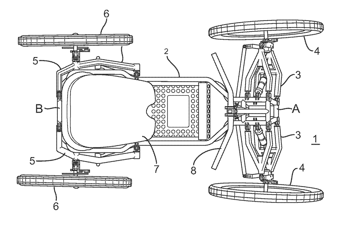
[0022]FIG. 1 schematically illustrates a top view of a human-propelled vehicle;

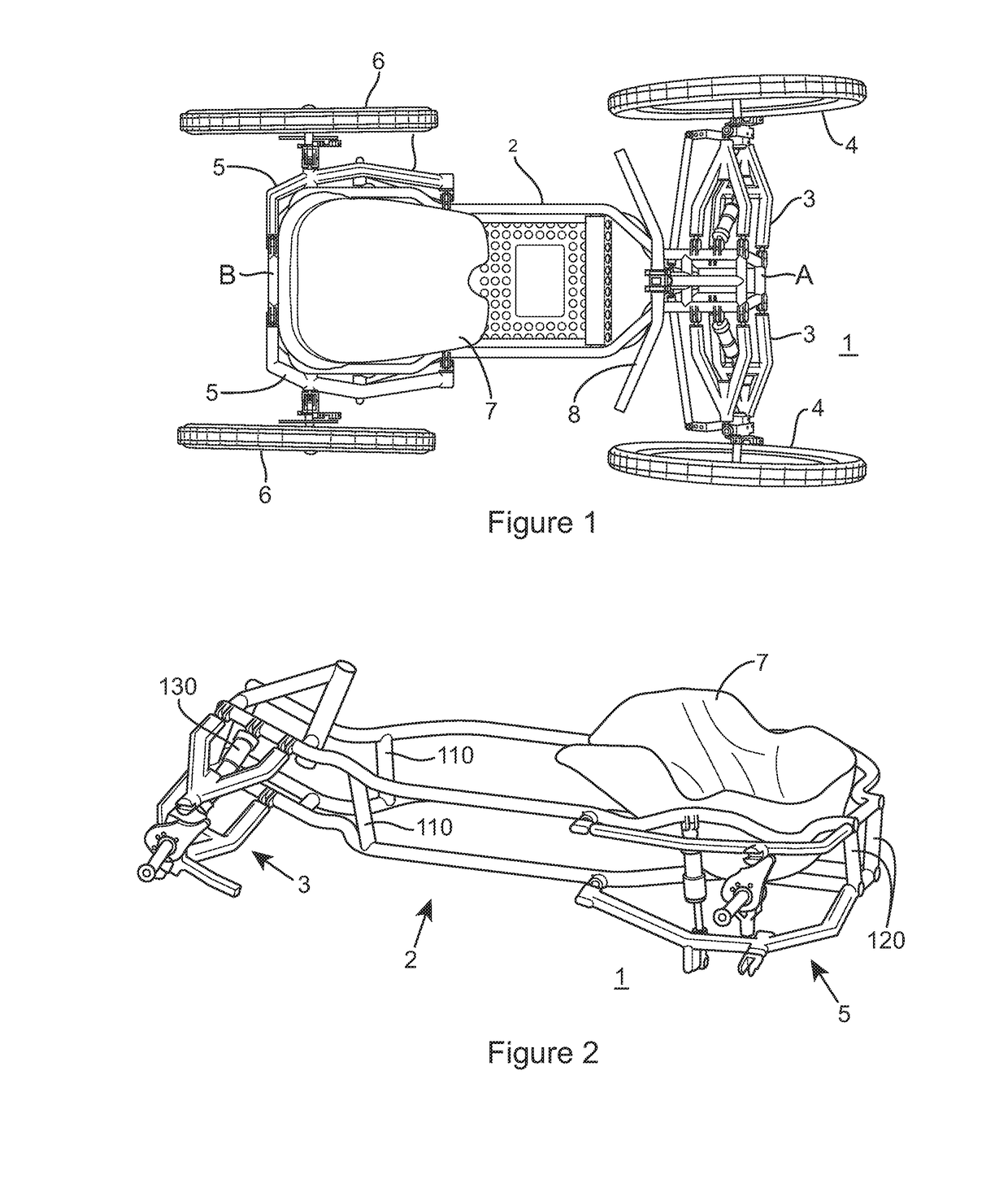
[0023]FIG. 2 schematically illustrates a 3D view of the human-propelled vehicle;

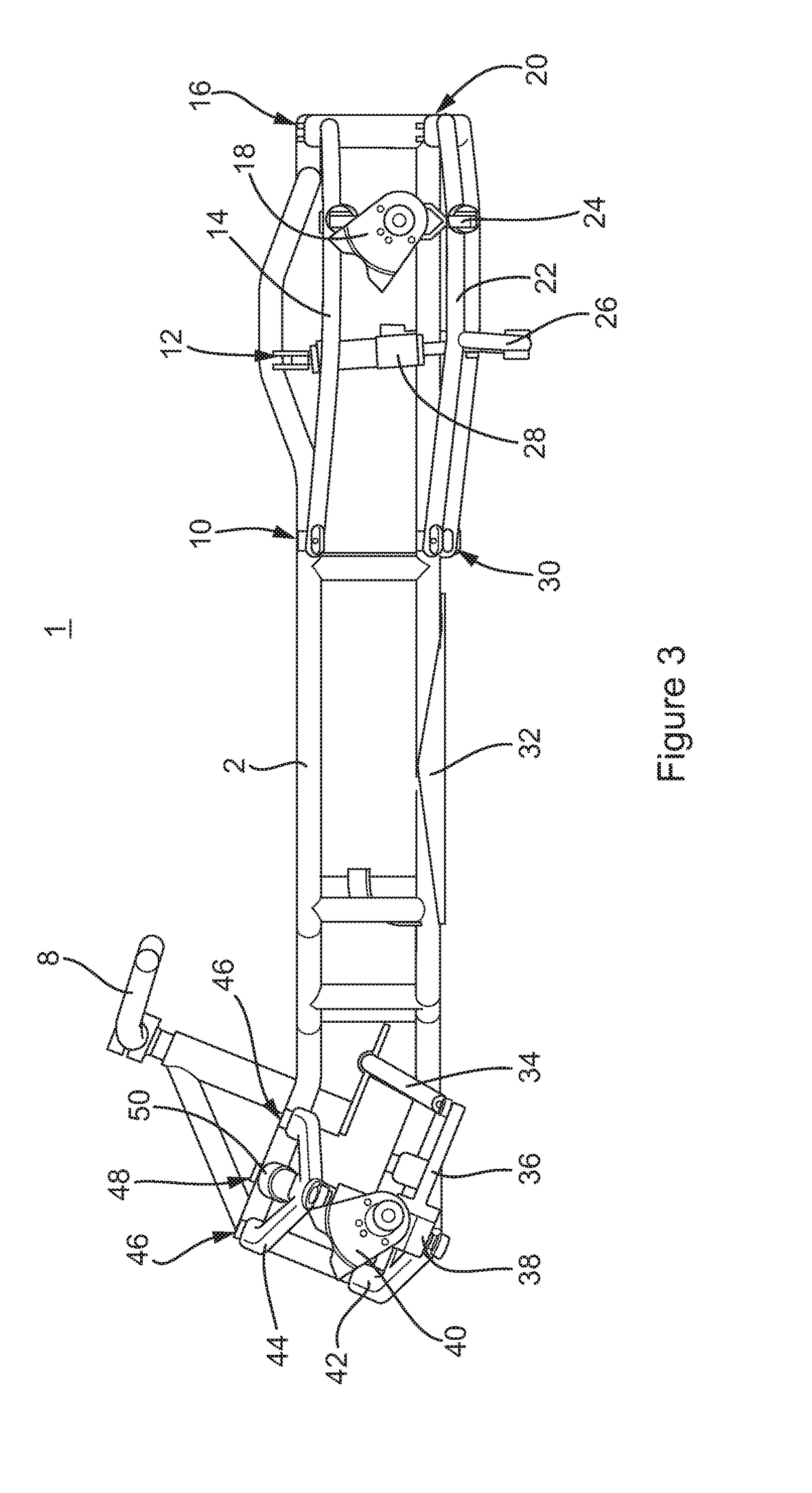
[0024]FIG. 3 schematically illustrates a side view of the human-propelled vehicle;

[0025]FIG. 4 schematically illustrates another top view of the human-propelled vehicle;

[0026]FIG. 5 schematically illustrates a front view of the human-propelled vehicle;

[0027]FIG. 6 schematically illustrates a bottom view of the human-propelled vehicle; and

[0028]FIG. 7 schematically illustrates a rear view of the human-propelled vehicle.

[0029]Referring first to FIG. 1, a top down view of a human propelled vehicle 1 is shown. The human propelled vehicle 1 comprises a chassis 2, a front wheel assembly 3, front wheels 4, a rear wheel assembly 5, rear wheels 6, a seat 7 and handlebars 8. In use, a rider sits in the seat 7 and is able to use h...


PUM


Abstract

A human-propellable vehicle (1) is described which comprises a chassis (2), and a rear wheel assembly (5) mounted to a rear portion of the chassis. The rear wheel assembly comprises a double wishbone suspension assembly, each wishbone (14, 22) of the double wishbone suspension assembly being coupled to the chassis at first and second coupling points, the second coupling point for each wishbone being closer to the rear of the chassis, and closer to the longitudinal axis of the vehicle, than the first coupling point for that wishbone. By using a double wishbone set up at the rear of the bike it is possible to control weight transfer more efficiently. By providing a second coupling point for each wishbone which is closer to the rear of the chassis, and closer to the longitudinal axis of the vehicle, than the first coupling point for that wishbone, it is possible to utilise a setup without having to adopt a higher seating position and without having to increase the rear wheel track beyond an acceptable width.

Description

FIELD OF THE INVENTION[0001]The present invention relates to a human-propellable vehicle. Embodiments of the present invention relate to a three or four wheeled bike having improved suspension. One embodiment of the present invention relates to a four wheel bicycle with gravity propulsion in which the suspension geometry and mounting points of the suspension components may improve vehicle dynamics.BACKGROUND TO THE INVENTION[0002]A four wheel gravity propelled downhill bicycle primarily aimed at disabled riders may require a wheel chair type appearance to the rear of the vehicle, to be suitable for the disabled rider. In particular, the bikes need to resemble a wheel chair at the rear to enable self-propulsion of the bike when not assisted by gravity. As a result, previous bikes tend to place the rider right at the back of the bike to achieve the “wheel chair” type design. However this creates a problem in as much as the weight distribution is not favourable to the application of th...

Claims


Application Information

Patent Timeline
Patent Type & Authority Applications(United States)
IPC IPC(8): B62K25/04B62K5/06B62J1/00B62K21/08B62K21/12B62D1/04B62K5/003B62K5/08
CPCB62K25/04B62K5/003B62K5/06B62K5/08B62K21/08B60Y2200/124B62D1/04B62J1/002B62K2005/001B60Y2200/122B62K21/12B62K3/16B62K19/30B60G3/20B60G7/001B60G7/008B60G7/02B62K25/00B60G2200/156B60G2200/1322
Inventor WILLIAMS, CALVIN JOHN LLEWELYNDAVIES, PAUL HOWARD
Owner GOWER COLLEGE SWANSEA
Why Eureka
Try Eureka