Control system for manual transmissions

Inactive Publication Date: 2017-03-30
BORG WARNER INC
View PDF2 Cites 3 Cited by
  • Summary
  • Abstract
  • Description
  • Claims
  • Application Information

AI Technical Summary

Benefits of technology

[0010]In this way, the present invention significantly improves the operation, functionality, and drivability of vehicles with conventional manual transmissions. Moreover, the present invention enables advantages related to clutch and transmission protection and longevity. Further, the present invention allows a vehicle operator to drive a manu

Problems solved by technology

However, these transmissions are typically complex, expensive to manufacture, heavy, difficult to service, and frequently perform poorly in stop-and-go traffic.
Further, these transmissions are typically controlled entirely electronically and, as a result, no clutch pedal is typically utilized, which is undesirable to operators who enj

Method used


Image

  • Control system for manual transmissions
  • Control system for manual transmissions
  • Control system for manual transmissions

Examples


Example

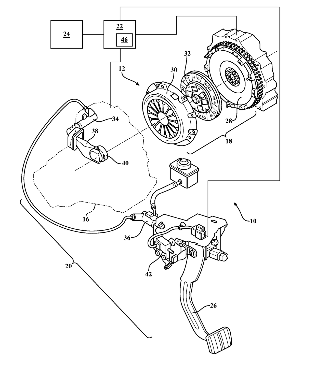
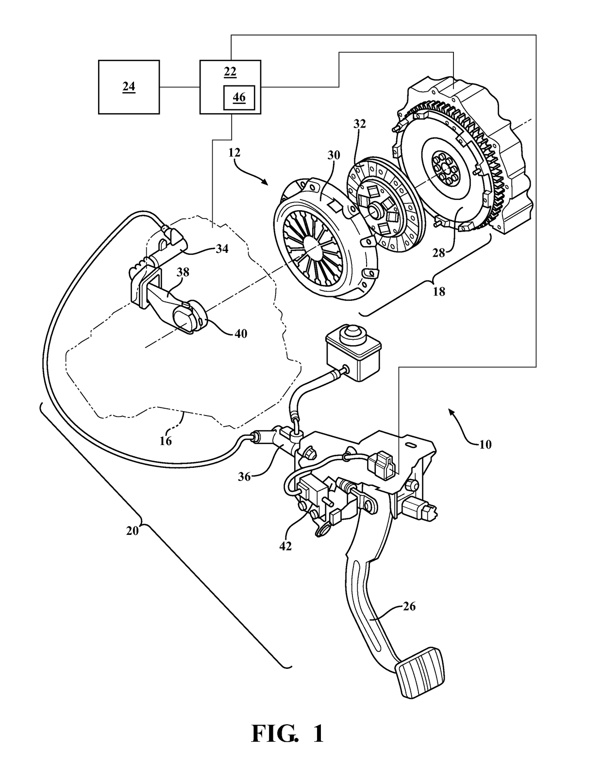
[0014]Referring now to the figures, where like numerals are used to designate like structure, a portion of a conventional automotive vehicle is generally indicated at 10 in FIG. 1. The vehicle 10 includes a powertrain 12 for propelling the vehicle. The powertrain 12 generally includes an engine 14, manual transmission 16, and clutch assembly 18. The vehicle 10 may also include a clutch actuation system, generally indicated at 20, an engine control unit (ECU) 22, and one or more input controls 24. Each of these components will be discussed in greater detail below.

[0015]The engine 14 generates rotational torque, which is selectively translated via the engine crankshaft (not shown, but generally known in the art) to the transmission 16 so as to drive the vehicle 10, as discussed in greater detail below. The engine 14 shown in FIG. 1 is typically a spark-ignition Otto-cycle engine 14, which is controlled by the ECU 22. However, those having ordinary skill in the art will appreciate that...


PUM


Abstract

A control system (44) for a clutch (18) of a manual transmission (16) in a vehicle (10) having an ECU (22), an engine (14), a pedal (26) having a sensor (42), a slave (34) in fluid communication with a master (36); and at least one input (24). The control system (44) includes a pump (50), a valve (52) in fluid communication with the slave (34) and pump (50), and a controller (46) responsive to the ECU (22) and operable in a plurality of modes for selectively cooperating with the pedal (26) to actuate the slave (34) and modulate the clutch (18) under predetermined engine (14) and vehicle (10) operating conditions. The controller (46) is movable between modes in response to signals from the ECU (22) representing predetermined changes in one or more of: engine speed, engine load, vehicle speed, transmission gear, pedal position, or input state.

Description

BACKGROUND OF INVENTION[0001]1. Field of Invention[0002]The present invention relates generally to automotive transmission systems and, more specifically, to a control system for manual transmissions.[0003]2. Description of the Related Art[0004]Conventional automotive powertrain systems that utilize manual transmissions known in the art typically include an internal combustion engine having a crankshaft in selective rotational communication with the manual transmission, a clutch assembly, and a hydraulic actuation system. The clutch assembly is used to selectively modulate engagement between the engine and transmission. To that end, the clutch assembly typically includes a flywheel operatively attached to the crankshaft, a pressure plate in rotational communication with an input shaft of the transmission and operatively attached to the flywheel, and a clutch disk disposed between the flywheel and the pressure plate. The hydraulic actuation system typically includes a master cylinder...

Claims


Application Information

Patent Timeline
IPC IPC(8): F16D48/06F16H63/46
CPCF16D48/068F16D2500/50841F16D2121/04F16D2500/1026F16D2500/10412F16D2500/1045F16D2500/3067F16D2500/30806F16D2500/3108F16D2500/3109F16D2500/3111F16D2500/31413F16D2500/31426F16D2500/3144F16D2500/5048F16H63/46F16D48/02
Inventor SCHWEKUTSCH, MICHAELBUCHANAN, MARK
Owner BORG WARNER INC
Why Eureka
Try Eureka