Opto-mechanical physical sensor with an improved sensitivity
- Summary
- Abstract
- Description
- Claims
- Application Information
AI Technical Summary
Benefits of technology
Problems solved by technology
Method used
Image
Examples
first embodiment
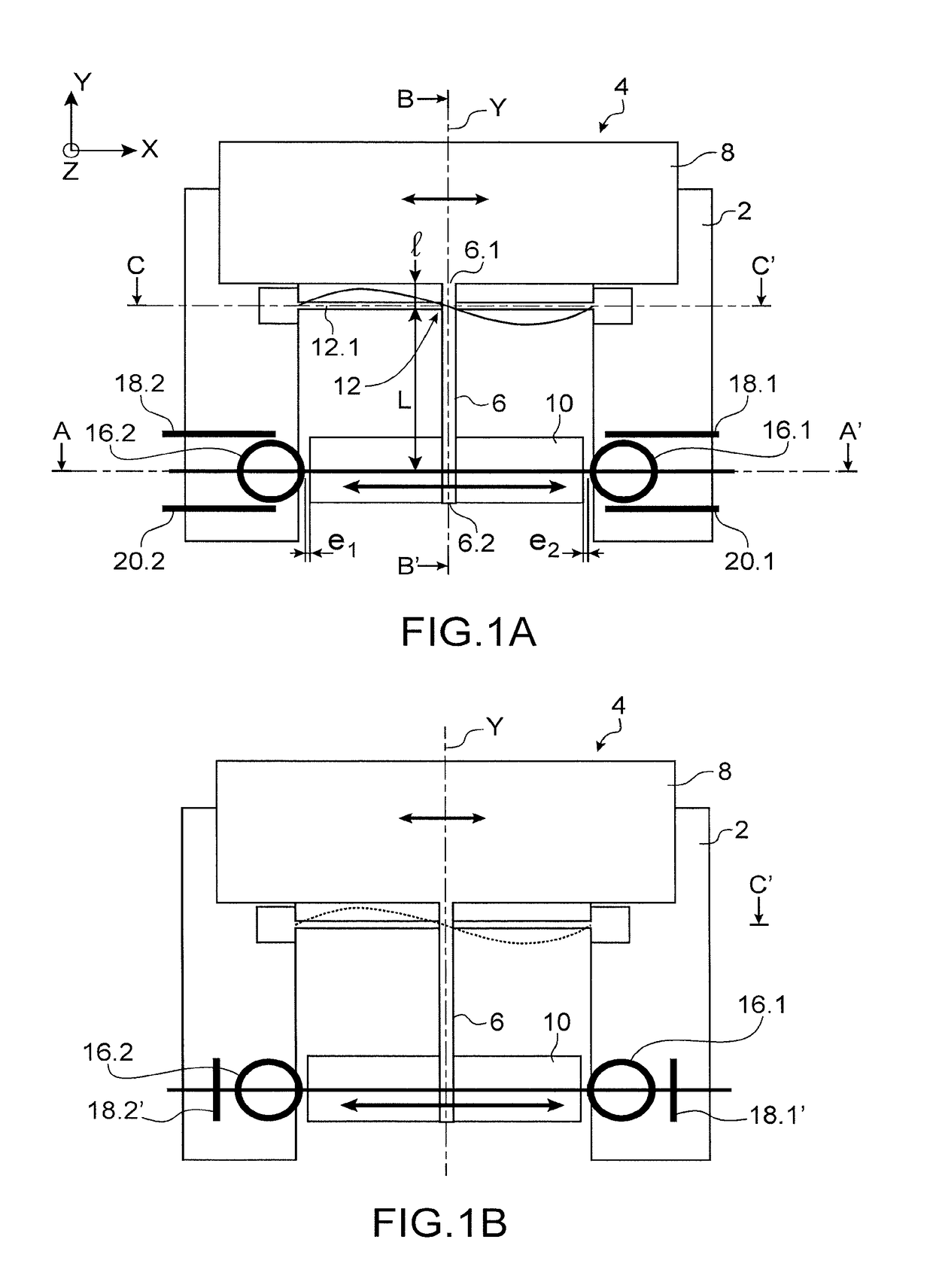
[0037]FIG. 1A is a top view of an exemplary embodiment of the sensor which is an inertial sensor, comprising a substrate 2 and a structure 4 suspended relative to the substrate 2.
[0038]The structure 4 is able to be moved relative to the substrate substantially in the plane of the sensor about an axis of rotation Z perpendicular to the plane of the sensor XY which is the plane of the sheet in the representation of FIG. 1A.
[0039]The structure 4 comprises a beam 6 having a longitudinal axis Y, a mass 8 located at a first longitudinal end 6.1 of the beam 6 and an influence element 10 located at a second longitudinal end 6.2 of the beam 6.
[0040]In the example represented, the influence element 10 is formed by a rigid plate.
[0041]The beam 6, mass 8 and influence element 10 assembly forms a rigid assembly. The structure is rotatably hinged about the axis Z relative to the substrate by means of a pivot connection 12.
[0042]In the following of the description, the beam 6 will be designated a...
second embodiment
[0120]The sensor therefore offers a greater sensitivity.
[0121]As for the first embodiment, the modification in the optical index of the resonator causes a variation in the frequency or an amplitude variation in the detection beam. From these measurements, the characteristics of the force applied to the mass can be determined.
[0122]In the example represented, a differential measurement is performed, two probe lasers and two photodetectors, one for each resonator, are then implemented. As for the first embodiment, the sensor can comprise only one resonator.
[0123]Under the same conditions as applied to the sensor of FIG. 1A, and by considering the perimeter variation of the optical resonators and by not considering the electrostrictive effect, the limit of detection at 3σ is Ing for a 100 ms integration time.
[0124]When the electrostrictive effect is taken into account, the response can be improved by a factor 2, the resolution can thereby be 0.5 ng. The influence of the electrostricti...
third embodiment
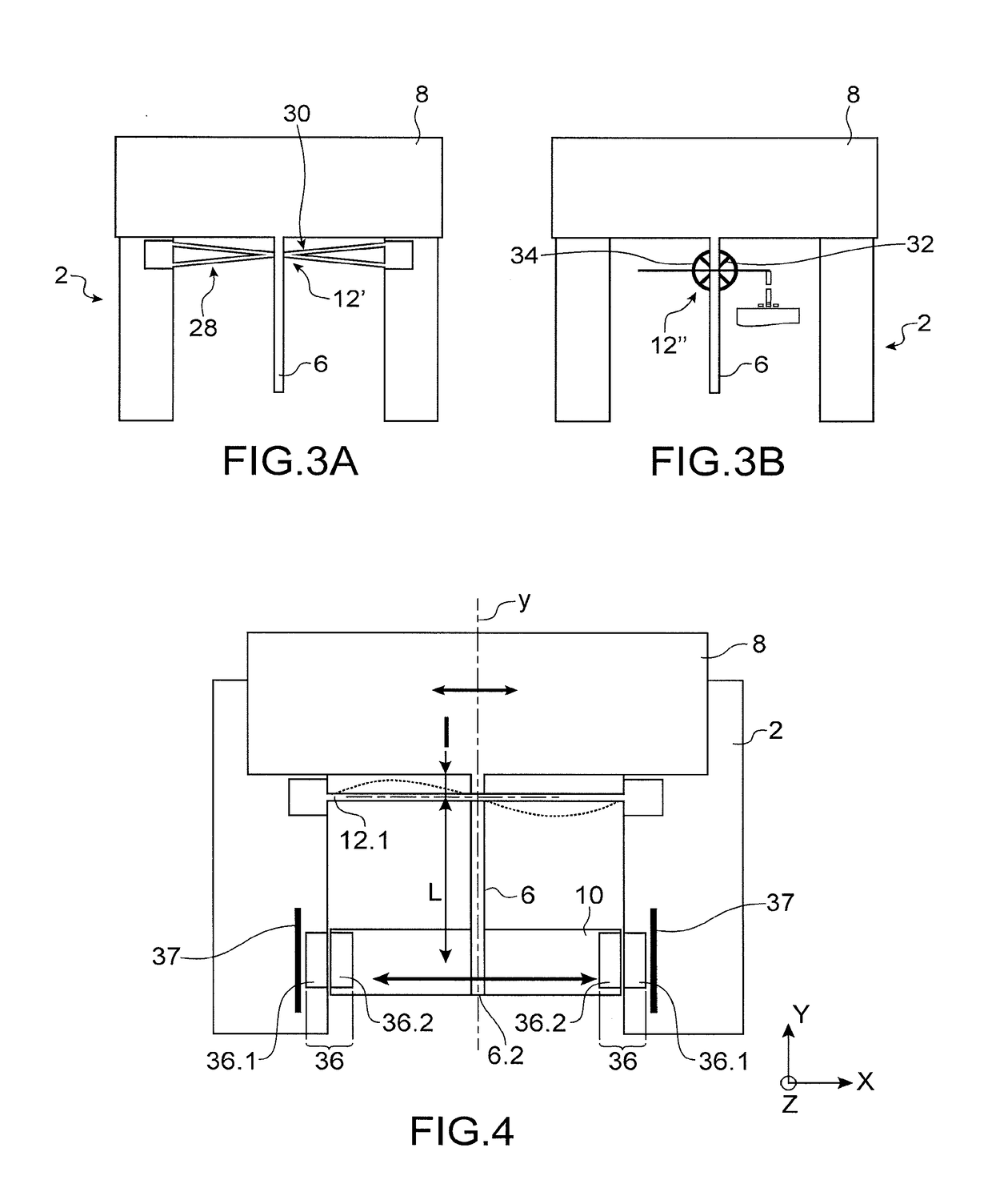
[0125]A sensor with a frequency detection will now be described.
[0126]The sensor has a structure similar to the sensor of FIG. 6A, thereby the same references are used again, and it further comprises means for vibrating the resonator(s) such that it (they) form(s) one or more mechanical resonators. Advantageously, the means optically actuate the resonator(s). The means comprise, for each resonator, for example an excitation light source which is amplitude-modulated at a mechanical resonance frequency of the resonator, this frequency is different from the frequency of the probe beam.
[0127]The excitation light source is for example a laser source designated a pump laser. The mechanical resonance frequencies can range from 10 MHz to 1 GHz depending on the materials and dimensions. They correspond to a natural frequency of the resonator cavity. The light source has an optical power sufficient to generate the movement through a photon radiation pressure. The power is for example between...
PUM
 Abstract
Description
Claims
Application Information
 - R&D
- Intellectual Property
- Life Sciences
- Materials
- Tech Scout
- Unparalleled Data Quality
- Higher Quality Content
- 60% Fewer Hallucinations
Browse by: Latest US Patents, China's latest patents, Technical Efficacy Thesaurus, Application Domain, Technology Topic, Popular Technical Reports.
© 2025 PatSnap. All rights reserved.Legal|Privacy policy|Modern Slavery Act Transparency Statement|Sitemap|About US| Contact US: help@patsnap.com


