
Volumetric three-dimensional display

a three-dimensional display and volumetric technology, applied in the field of three-dimensional displays, can solve the problems of inability to employ an arrangement of elements, inability to achieve close-packing of spheres, and inability to achieve spherical voxels

Inactive Publication Date: 2017-03-30
BRINDISI THOMAS J
View PDF7 Cites 8 Cited by
  • Summary
  • Abstract
  • Description
  • Claims
  • Application Information

AI Technical Summary

Benefits of technology

[0006]Despite the fact that regular tetrahedral structures cannot fully tessellate a volume, Applicant has found that by utilizing a close-packed lattice arrangement of elements in a novel volumetric three-dimensional display, certain key functional advantages can be derived that generate meaningfully enhanced performance. Utilizing four different-colored emitters in this arrangement permits a scheme wherein a smooth and uniform flow of voxels and boundaries that is impossible in the conventional arrangement can be achieved. Using a conventional RGB emitter stack (or similar full-color assemblage) for each of the elements in a close-packed lattice can provide related unique benefits.

Problems solved by technology

Even if one in the field had contemplated trying to depart from the existing model, and if they happened to consider the notion of space-filling in the process, the possibility of employing an arrangement of elements that is derived from the geometry of the close-packing of spheres would not have appeared to be a good candidate.
For one thing, a spherical voxel would be impractical to construct.
(A voxel might be formed of a spherical-shaped diffusing material, but the opacity of the resulting extent of diffusing material is not desirable for a volumetric three-dimensional display, if not untenable depending on the density and depth of elements).

Method used


Image

  • Volumetric three-dimensional display
  • Volumetric three-dimensional display
  • Volumetric three-dimensional display

Examples


Embodiment Construction

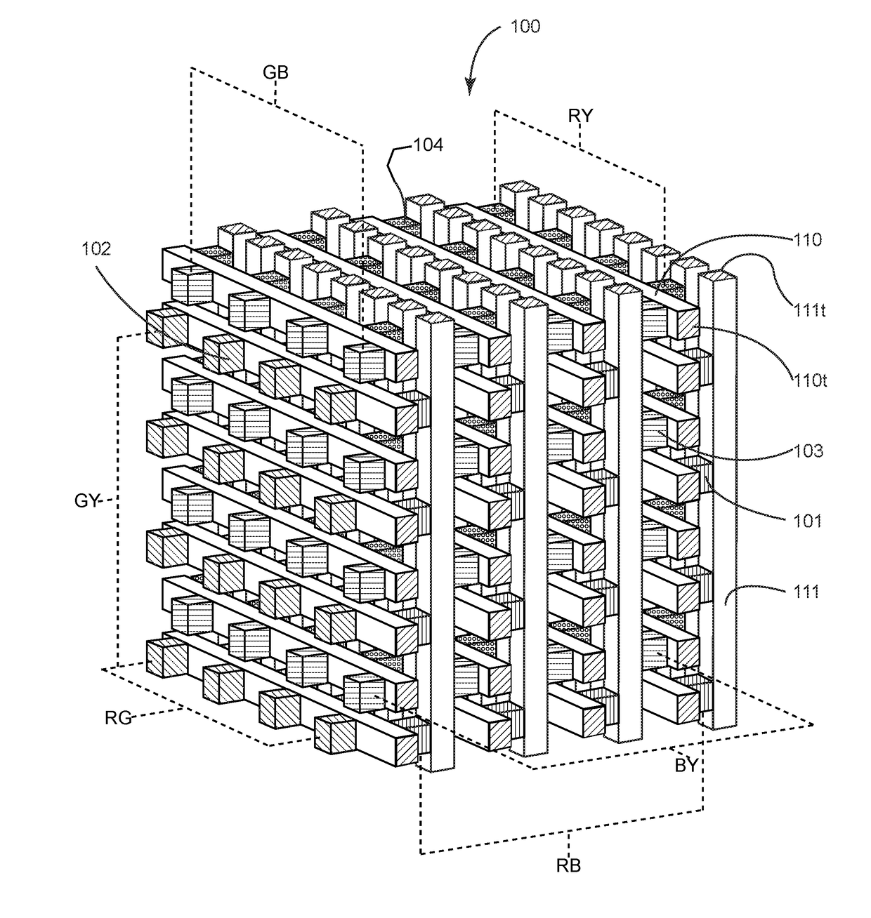
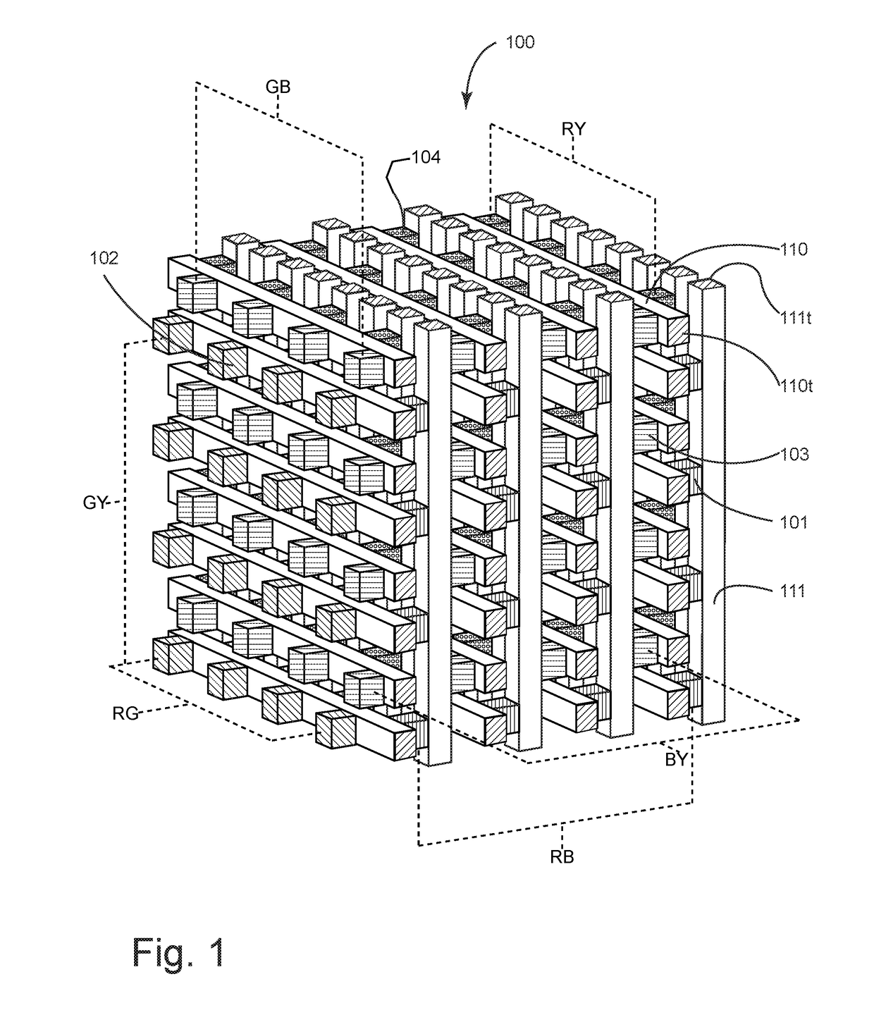
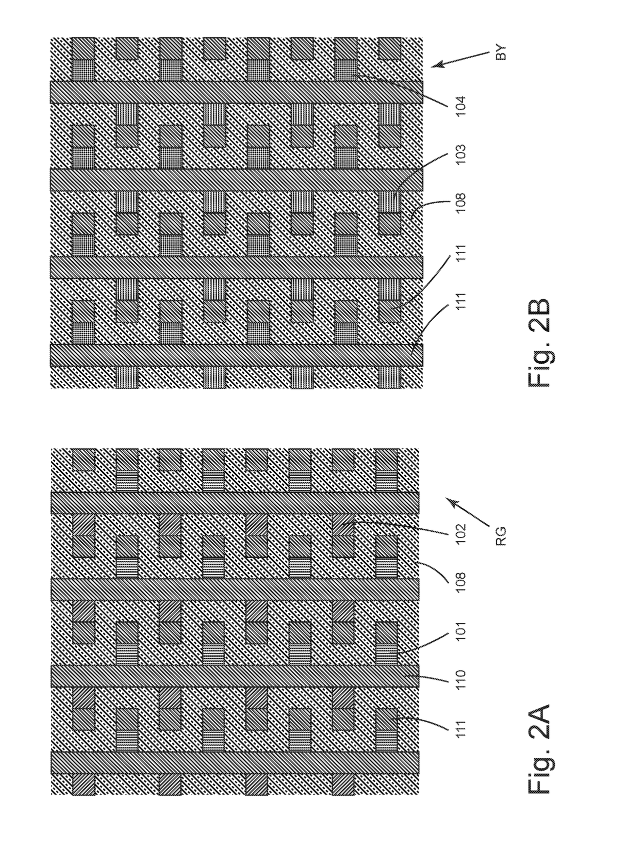
[0017]The figures depict a portion of a volumetric display 100 having a basic face-centered cubic arrangement of emitters 101-104 (which typically comprise the layers [such layers not depicted here] of a conventional inorganic or organic light emitting diode) including red emitters 101, green emitters 102, blue emitters 103, and yellow emitters 104. The structure is arranged so that there are repeating identically-oriented, evenly-spaced, regular tetrahedral shaped voxels comprising one of each emitter. (The tetrahedrons' edges are defined by imaginary lines connecting the emitters' centerpoints. “Centerpoint” as used herein generally just means the geometric three-dimensional center of the emitter structure, but for some emitters the source of light emission may be sufficiently separate from the geometric center as to behoove a mathematical assessment of the position of the center of the source as opposed to an overall diode feature or the like). The conductors 110 and 111 are pref...


PUM


Abstract

Novel arrangements of elements (e.g., individual emitters or stacks thereof) produce three-dimensional full-color light-emitting displays. In an embodiment, planar arrays of regularly-spaced elements and electrical conductors can be configured together by staggering the layers' respective lateral positioning and controlling the pitch between layers. Various advantages may include smooth flow of voxels and boundaries and / or enhanced three-dimensional appearance versus conventional direct stacks.

Description

CROSS-REFERENCE TO RELATED PATENT APPLICATIONS[0001]This application is a continuation of U.S. patent application Ser. No. 14 / 777,455, which was the national stage entry of PCT Application No. PCT / US14 / 029922 filed Mar. 15, 2014, and claims benefit of the priority of U.S. Provisional Patent Application Ser. No. 61 / 801,437 filed Mar. 15, 2013.FIELD OF THE INVENTION[0002]The present invention relates to three-dimensional displays, and in particular to volumetric, three-dimensional displays.BACKGROUND[0003]It is believed that hitherto, the obvious, realistically useful way to lay out a three-dimensional display comprising light emitting diodes has been to utilize identical layers (e.g., a two-dimensional OLED display) that repeat directly upwardly in the z axis, one atop the next. This has been done at least since U.S. Pat. No. 5,929,572 to Whitesell and GB Patent Application 2376555 to Eickhoff, through U.S. Patent Application Publication No. 2004 / 0145538 to Uchida et al., U.S. Pat. N...

Claims


Application Information

Patent Timeline
Patent Type & Authority Applications(United States)
IPC IPC(8): G02B27/22H01L25/075H01L27/32H04N13/04
CPCG02B27/2278H04N13/0422H04N13/0488H04N2213/001H01L27/3209H01L27/3213H01L27/3218H01L25/0756G09G3/3208G09G2300/0452H01L2924/0002G09G3/003H04N13/324H04N13/388G02B30/50H10K59/90H10K59/32H10K59/351H10K59/353H01L2924/00G02B30/52H10K50/00G06T11/008G06T15/08G06T2200/04
Inventor BRINDISI, THOMAS J.
Owner BRINDISI THOMAS J
Learn More