Modulation method for the boost converter operating mode of a push-pull converter

Active Publication Date: 2017-03-30
ROBERT BOSCH GMBH
View PDF8 Cites 2 Cited by
  • Summary
  • Abstract
  • Description
  • Claims
  • Application Information

AI Technical Summary

Benefits of technology

[0012]According to one preferred modification to the invention, a diode can be connected in each case in an anti-parallel manner to the low-voltage-side and high-voltage-side switching devices. In this modification, the diodes can be used for rectification and the switching devices do not have to be designed as synchronous rectifiers.
[0013]According to one preferred modification to the invention, the high-voltage-side rectification elements can be designed as switching devices. In consecutive modulation cycles in the firs

Problems solved by technology

This makes a complicated configuration

Method used


Image

  • Modulation method for the boost converter operating mode of a push-pull converter
  • Modulation method for the boost converter operating mode of a push-pull converter
  • Modulation method for the boost converter operating mode of a push-pull converter

Examples


Example

[0021]In the figures of the drawings, identical reference signs denote identical or functionally identical elements.

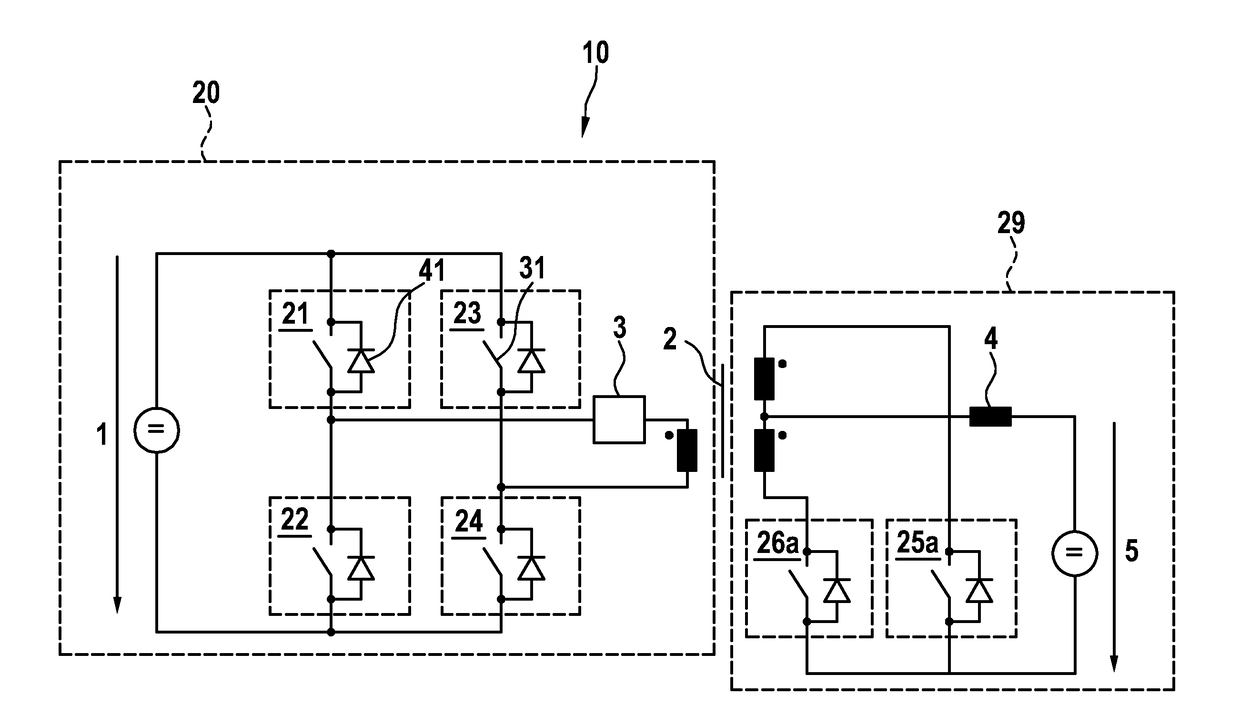
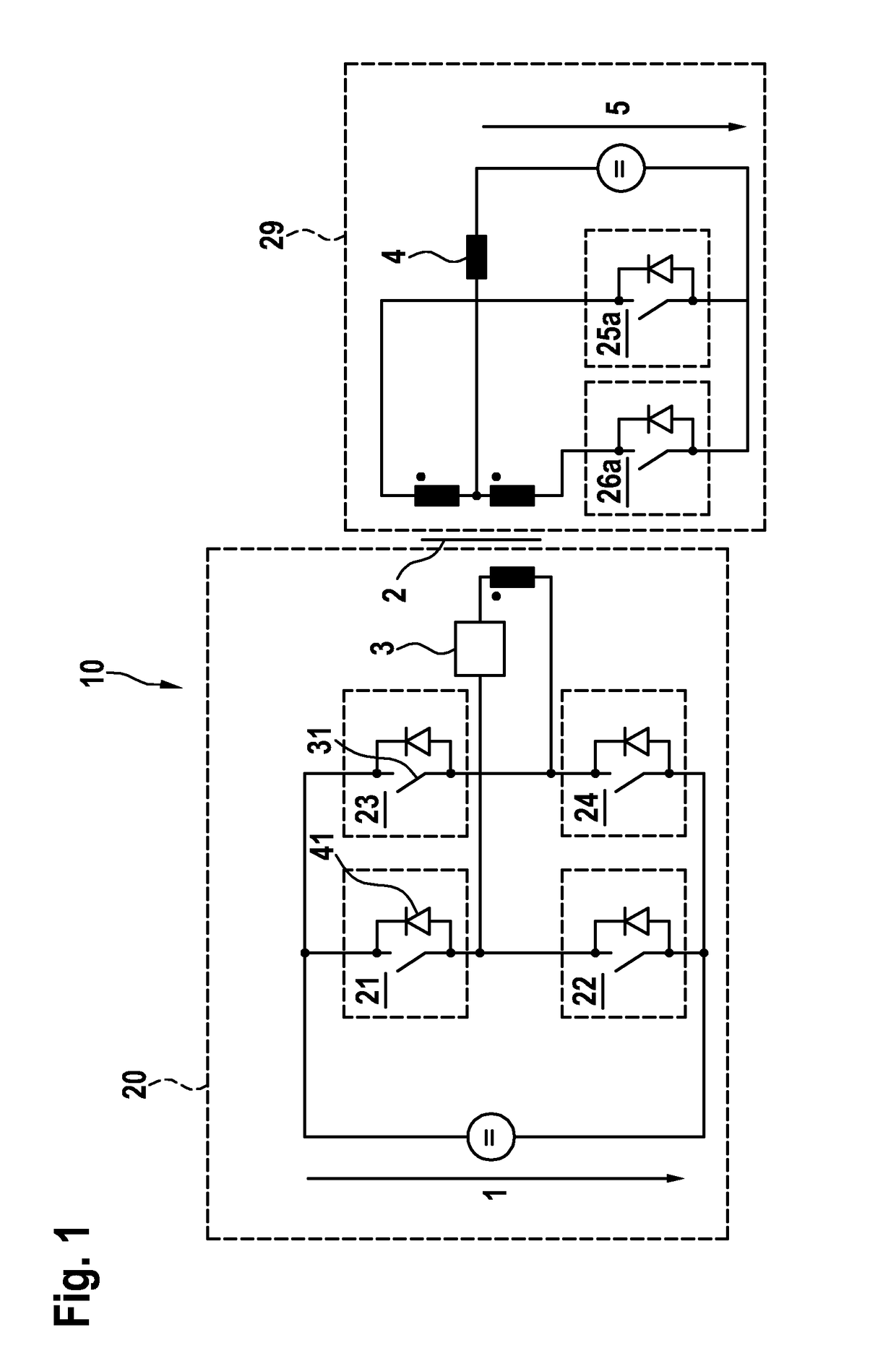
[0022]FIG. 1 shows a schematic depiction of an exemplary bidirectional push-pull converter.

[0023]In FIG. 1, the reference sign 10 denotes the push-pull converter. A full-bridge circuit comprising switching devices 21, 22, 23, 24 can be implemented here in a high-voltage-side circuit 20. A low-voltage-side circuit 29 is designed as a center-tap connection comprising switching devices 25a, 26a as well as a throttle 4. The high-voltage-side circuit 20 and the low-voltage-side circuit 29 are furthermore connected to one another in a galvanically isolating manner by means of a transformer 2. A current sensor device 3 is located within the high-voltage-side circuit, said current sensor device being designed to measure the current through the transformer 2. The switching devices 21, 22, 23, 24, 25a, 26a each comprise a transistor 31 and a diode 41. A DC voltage 1 can be appli...


PUM


Abstract

The invention relates to a method for modulating the boost converter operating mode of a push-pull converter having a low-voltage-side circuit, having a first low-voltage-side switching device and a second low-voltage-side switching device; having a transformer having a high-voltage-side winding; and having a high-voltage-side circuit, which is configured as a full-bridge rectifier, having a first and a second rectification element which form a first half-bridge and a third and a fourth rectification element which form a second half-bridge; wherein the method comprises the steps of closing the first low-voltage-side switching device whilst simultaneously short-circuiting the high-voltage-side winding via the first or the fourth rectification element during a first time segment; opening the rectification element used for short-circuiting the high-voltage-side winding during a second time segment; opening the first low-voltage-side switching device and closing the second low-voltage-side switching device whilst simultaneously short-circuiting the high-voltage-side winding via the third or the fourth rectification element in the second half-bridge during a third time segment; and opening the rectification element used for short-circuiting the high-voltage-side winding during a fourth time segment.

Description

BACKGROUND OF THE INVENTION[0001]The invention relates to a method for modulating the boost converter operating mode of a push-pull converter. The invention particularly relates to a method for modulating the boost converter operating mode of a bidirectional push-pull converter.[0002]Although the present invention and the underlying set of issues are explained with the help of a bidirectional push-pull converter, said invention can also be applied to any other push-pull converters, in which a boost converter operating mode is provided.[0003]Bidirectional DC-DC converters are typically used in situations where electrical energy is to be transmitted in two directions. Said bidirectional DC-DC converters are therefore useful in hybrid electric vehicles for transmitting energy for a high-voltage network to a low-voltage network and vice versa. For example, a 12 volt battery can be charged with the help of a DC-DC converter in the buck converter operating mode, whereas the boost converte...

Claims


Application Information

Patent Timeline
IPC IPC(8): H02M3/337H02M1/08
CPCH02M3/3378H02M2001/0009H02M1/08H02M3/33584H02M1/0009Y02B70/10
Inventor TASTEKIN, DAVID
Owner ROBERT BOSCH GMBH
Why Eureka
Try Eureka