Methods for diverting lightning current from skin fasteners in composite, non-metallic structures
- Summary
- Abstract
- Description
- Claims
- Application Information
AI Technical Summary
Benefits of technology
Problems solved by technology
Method used
Image

Examples
Embodiment Construction
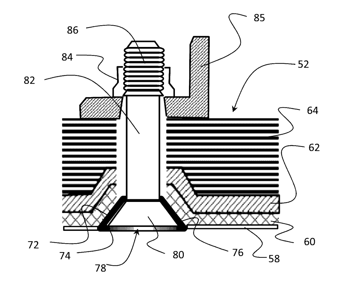
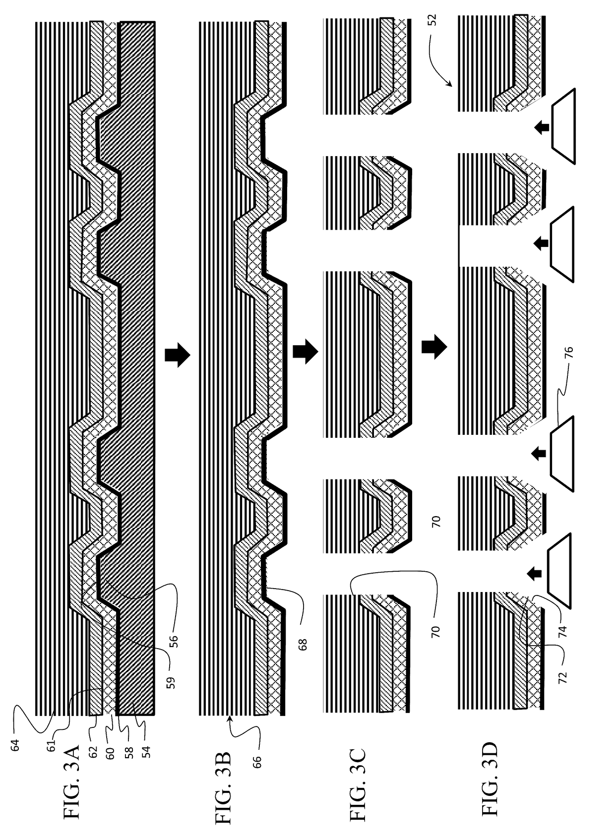
[0018]Embodiments disclosed herein provide lightning and / or other forms of electrical current dissipation in a first embodiment through electrical contact between a conical washer and outer layers of a composite structure and a conical head of a fastener extending through the composite structure. A shaft of the fastener is received in the composite structure in a clearance fit hole. In a further embodiment, current dissipation is enhanced through direct electrical connection between a conductive layer co-cured in a composite structure and fasteners in the composite structure. The co-cured conductive layer extends inside a portion of the fastener holes and makes contact with heads of the fasteners or a conical washer interfacing the fastener head into the countersink after installation. The composite structure is realized by first laying down a fiber glass or surfacing film as a protective outer layer, a conductive layer such as a wire mesh, an adhesive layer (which may be integrated...
PUM
| Property | Measurement | Unit |
|---|---|---|
| Thickness | aaaaa | aaaaa |
| Thickness | aaaaa | aaaaa |
| Thickness | aaaaa | aaaaa |
Abstract
Description
Claims
Application Information