Insulation apparatus and method

Active Publication Date: 2017-04-13
LNT MARINE PTE LTD
View PDF6 Cites 6 Cited by
  • Summary
  • Abstract
  • Description
  • Claims
  • Application Information

AI Technical Summary

Benefits of technology

[0020]Advantageously the panels may be 1 metre square panels with a centrally located fixing hole. This allows the panels to be easily handled by an installation team and tessellated along the hold space wall. Other shapes may also be used depending on the profile and shape of the vessel hold space. For example curved sections may be employed at

Problems solved by technology

They are extremely safe but inherently expensive to manufacture and maintain.
The cost of constructing and operating

Method used


Image

  • Insulation apparatus and method
  • Insulation apparatus and method
  • Insulation apparatus and method

Examples


Embodiment Construction

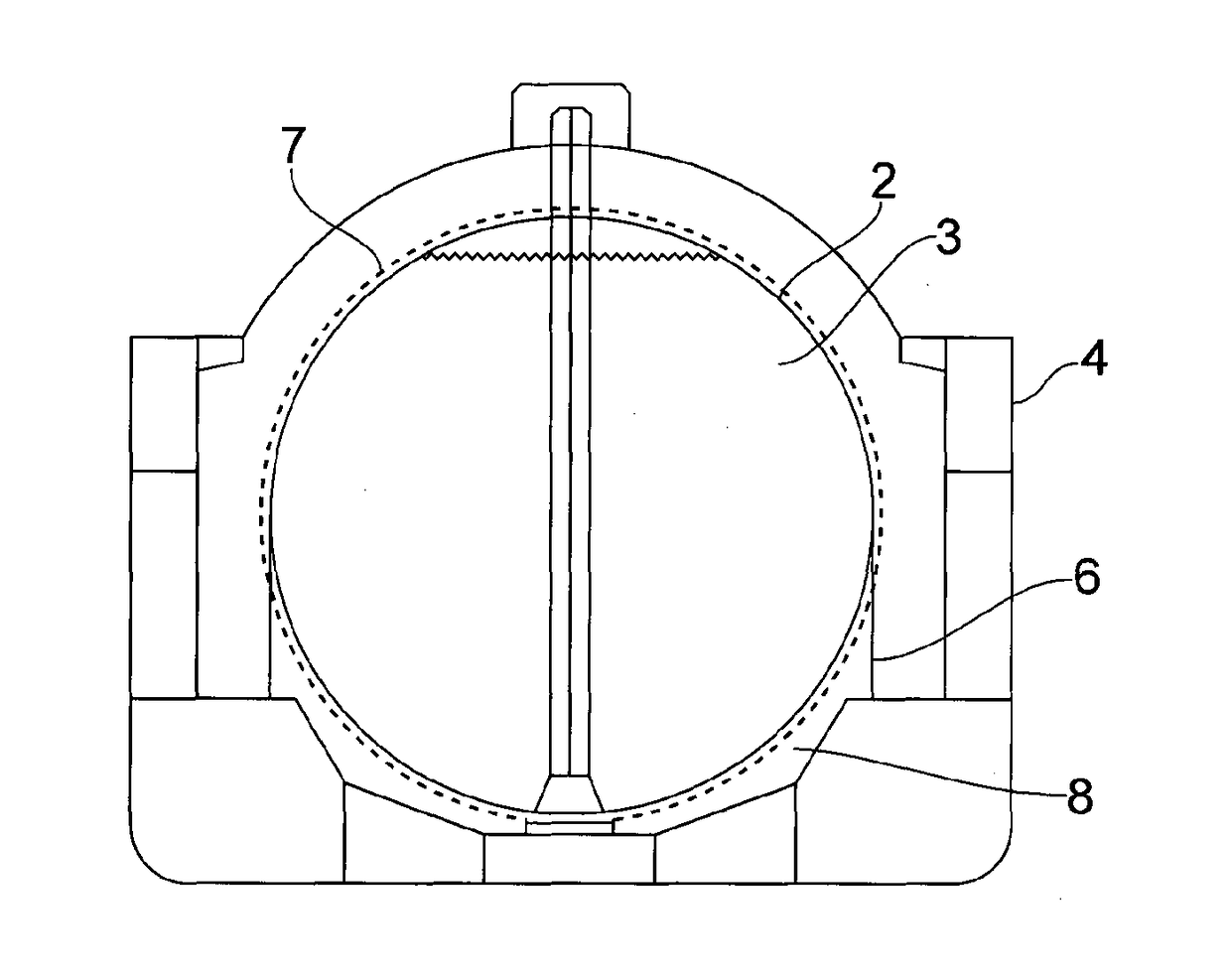
[0070]FIG. 1 shows a cross-section of an LNG cryogenic transport vessel comprising a spherical containment hold. Such a vessel is commonly used to transport large quantities of LNG and other cryogenic liquids.

[0071]The conventional marine vessel (ship) 1, commonly known as a “Moss design”, IMO type B comprises a spherical primary containment hold 2 which is arranged to contain the LNG cargo 3. The upper limit of the LNG within the hold 2 is shown. Commonly an LNG holder will contain multiple holds 2 mounted along the length of the holder. Only one is shown for illustration.

[0072]The hold 2 is mounted within the hull of the ship 1 and is supported about its waist 5 by a skirt 6. Thus, the hold 2 is spaced from the hull 4 by the voids 8.

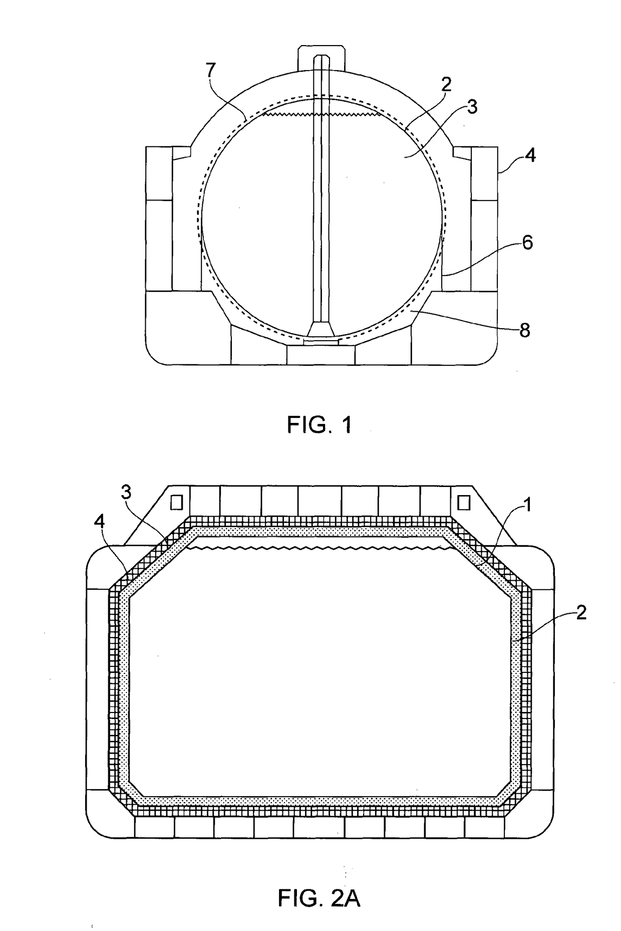
[0073]The hold contains a centrally located pipe tower and a drip tray beneath the hold within the void 8. The hold 2, forming the primary barrier, is surrounded by an insulation layer 7.

[0074]The hold 2 is itself insulated and the insulation in combin...


PUM

PropertyMeasurementUnit
Thicknessaaaaaaaaaa
Flexibilityaaaaaaaaaa
Shapeaaaaaaaaaa

Abstract

The invention relates to a marine vessel cryogenic barrier which is formed of a plurality of individual panels, each panel being arranged to align with an adjacent panel on an inner surface of a hold space of a marine vessel and comprising a single coupling means at the centre of the panel and an impervious layer on a surface of the barrier facing the hold space.

Description

BACKGROUND[0001]The present invention relates to an insulation system and method for insulating marine vessels. In particular, but not exclusively, the invention relates to vessels that are adapted to transport cryogenic liquids. Examples of such liquids include liquefied natural gas (LNG), liquefied propane gas (LPG) or liquefied ethylene gas (LEG).[0002]The invention can also be applied to other applications where insulation is required.[0003]International agreements determine the type and construction of marine vessels / ships which may be used to transport cryogenic liquids. Specifically, the regulations define how the cryogenic liquid is safely contained on the ship and importantly how the liquid can be contained should a hold fail.[0004]Cryogenic transport ships are designed according to regulations that require the containment holds to have very high integrity. The International Maritime Organisation (IMO) sets these regulations. Holds must be constructed such that the holds do...

Claims


Application Information

Patent Timeline
IPC IPC(8): B63B25/16F17C3/02F17C3/04
CPCB63B25/16F17C3/04F17C3/025B63B2231/40B63B2231/10F17C2203/0333F17C2270/0107F17C2203/0624F17C2203/0639F17C2203/0646F17C2221/033F17C2221/035F17C2260/033F17C2203/0358B63B2025/087F17C2201/052F17C2203/035F17C2203/0619F17C2203/0621F17C2203/066F17C2223/033F17C2223/031F17C2223/0161B63B35/28B65D90/06B63B3/68
Inventor NIKOLAISEN, PER IVAR
Owner LNT MARINE PTE LTD
Why Eureka
Try Eureka