Rotary machine having magnetic and mechanical bearings

Active Publication Date: 2017-04-13
SKF MAGNETIC MECHATRONICS
View PDF1 Cites 4 Cited by
  • Summary
  • Abstract
  • Description
  • Claims
  • Application Information

AI Technical Summary

Benefits of technology

The patent text describes a technical solution to reduce power consumption and manufacturing costs in a bearing system. The solution involves replacing the axial magnetic bearing with an axial mechanical thrust bearing. This change allows for smoother rotor movement and reduces wear on the bearing. Additionally, the use of elastic means allows for decoupling of the radial magnetic bearing function from the axial mechanical thrust bearing. This ensures that the radial magnetic bearing does not become disturbed and can actively control the rotor movement and position.

Problems solved by technology

Furthermore, rotary machines having constant, unidirectional thrust load, such as for example flywheels, only requires good dynamic performances of the radial magnetic bearings.
Indeed, the axial magnetic bearing only supports the rotor weight.

Method used


Image

  • Rotary machine having magnetic and mechanical bearings
  • Rotary machine having magnetic and mechanical bearings
  • Rotary machine having magnetic and mechanical bearings

Examples


first embodiment

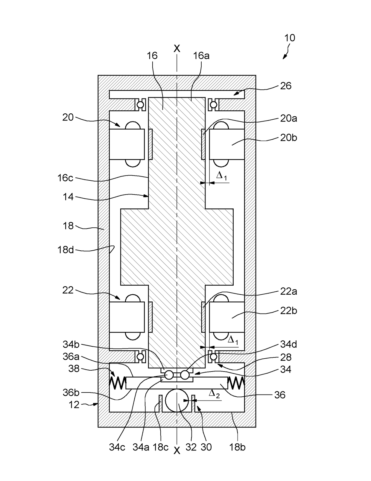
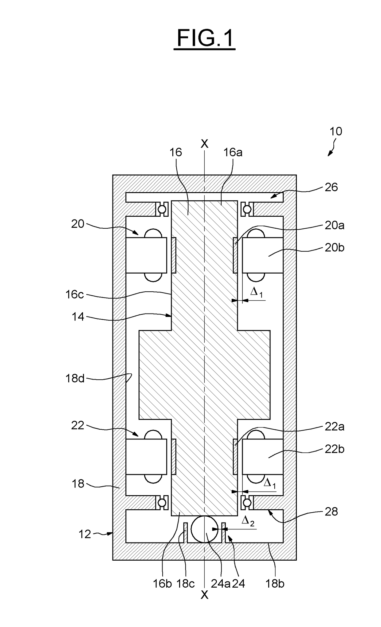
[0027]a rotary machine 10 is illustrated on FIG. 1; the rotary machine 10 may for example be a flywheel, or any rotary machine having a vertical rotor arrangement.

[0028]The rotary machine 10 provides a stator 12 and a rotor 14 having a shaft 16 rotating around a vertical axis X-X. The rotor shaft 16 is supported rotatably with respect to a casing 18 of the stator 12 by two radial magnetic bearings 20, 22 and an axial mechanical thrust bearing 24. The two radial magnetic bearings 20, 22 may be identical and arranged at opposite ends 16a, 16b of the rotor shaft 16.

[0029]Each radial magnetic bearing 20, 22 provides an annular armature 20a, 22a made of ferromagnetic material mounted on an outer cylindrical surface 16c of the rotor shaft 16 and a stator armature 20b, 22b secured to the stator casing 18. The stator armatures 20b, 22b each provides, in a conventional manner, a stator magnetic circuit having one or more annular coils and ferromagnetic body and are placed facing the rotor ar...
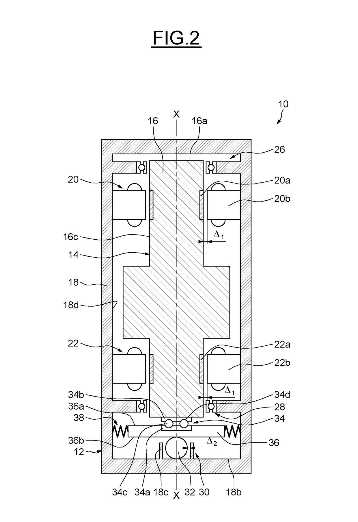
second embodiment

[0042]The second embodiment has been illustrated on the basis of an axial mechanical thrust bearing providing a rolling bearing provided with at least one row of rolling elements radially disposed between the inner and outer rings. Alternatively, the bearing may be a plain bearing or a sliding bearing providing one or two rings.

[0043]As an alternative, the embodiments illustrated on the Figures may be applied to a rotary machine having an axial magnetic bearing (not shown). In case the rotary machine provides an axial magnetic bearing, the axial mechanical thrust bearing comes into service when the axial magnetic bearing fails due to an electrical power cut or if its load capacity is exceeded. The axial mechanical thrust bearing provides a safety bearing without disturbing the radial magnetic bearings. In normal operation there is thus a mechanical gap between the axial mechanical thrust bearing and the shaft.

[0044]Thanks to the invention, manufacturing costs of the rotary machine a...


PUM


Abstract

A rotary machine provides a stator having a stator casing, and a rotor shaft having a rotational axis and supported in the stator casing by at least one radial magnetic bearing. The rotary machine further provides an axial mechanical thrust bearing being disposed proximate a radial surface of one end of the rotor shaft, the axial mechanical thrust bearing, including a rolling element located on the rotational axis of the rotor shaft.

Description

CROSS REFERENCE TO RELATED APPLICATIONS[0001]This application claims priority to European patent application no. 15306587.5 filed on Oct. 8, 2015, the contents of which are fully incorporated herein by reference.FIELD OF THE INVENTION[0002]The present invention relates to the field of rotary machines providing magnetic bearings for supporting the weight and load of a rotor of the rotary machine by active magnetic bearings thanks to magnetic fields. In particular, the invention relates to an auxiliary mechanical bearing for a radially magnetically suspended rotor system.BACKGROUND OF THE INVENTION[0003]It is known to provide axial and radial magnetic bearings in rotary machines having a vertical rotor arrangement and to provide auxiliary mechanical touch down bearings supporting the rotor in case of failure of the magnetic bearings, for example if the magnetic bearings are overloaded or if the electrical or electronic control system fails.[0004]Magnetic bearings operate without mecha...

Claims


Application Information

Patent Timeline
IPC IPC(8): F16C32/04H02K5/16H02K7/09F16C27/00
CPCF16C32/0402F16C27/00H02K7/09F16C32/0476H02K5/161F16C32/048F16C19/12F16C19/50H02K2205/03F16C17/08F16C19/10F16C27/04F16C32/0442F16C32/0487F16C2361/55Y02E60/16
Inventor SCHROEDER, ULRICHCARRASCO, EDUARDO
Owner SKF MAGNETIC MECHATRONICS
Why Eureka
Try Eureka