Lighting apparatus

Active Publication Date: 2017-04-20
PANASONIC INTELLECTUAL PROPERTY MANAGEMENT CO LTD
View PDF0 Cites 2 Cited by
  • Summary
  • Abstract
  • Description
  • Claims
  • Application Information

AI Technical Summary

Benefits of technology

[0011]According to a lighting apparatus according to an aspect of the present disclosure, unevenness of visible light radiated from the light emitter can be suppressed by suppressing the unevenness at the stage of the laser light which is the excitatio

Problems solved by technology

Conventionally, in a lighting apparatus, etc., there are instances where light, is not emitted evenly from the light exiting face, and unevenness such as illumination unevenness and color unevenness occurs in an irradiation region which is the region that is illuminated when an object is

Method used


Image

  • Lighting apparatus
  • Lighting apparatus
  • Lighting apparatus

Examples


Example

Embodiment 1

[0026]An embodiment is described below.

[0027]{Configuration of Lighting Apparatus]

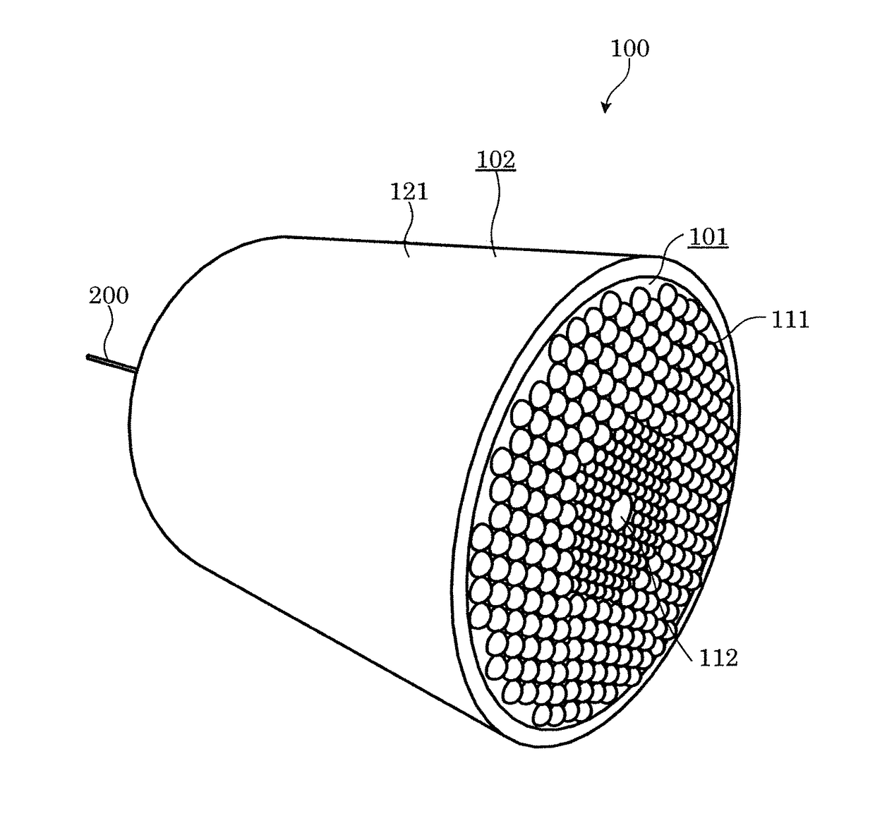
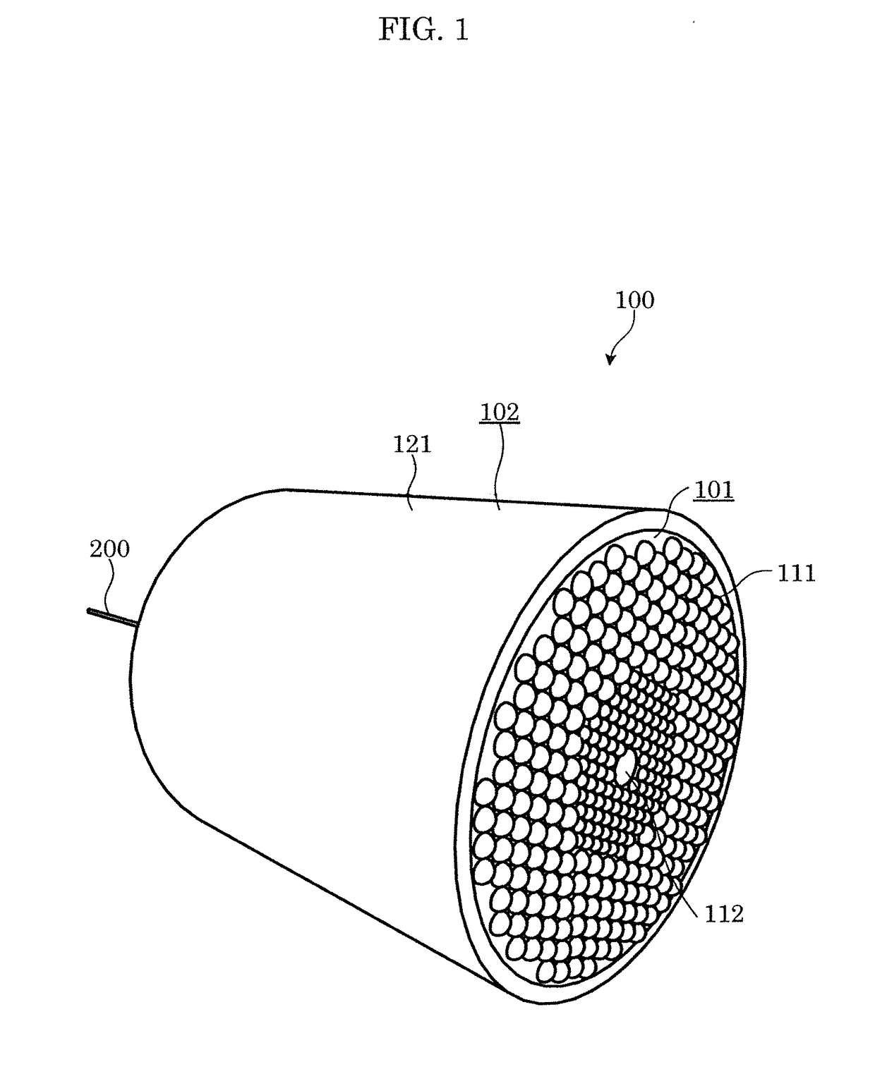
[0028]FIG. 1 is a perspective view illustrating an external appearance of a lighting apparatus.

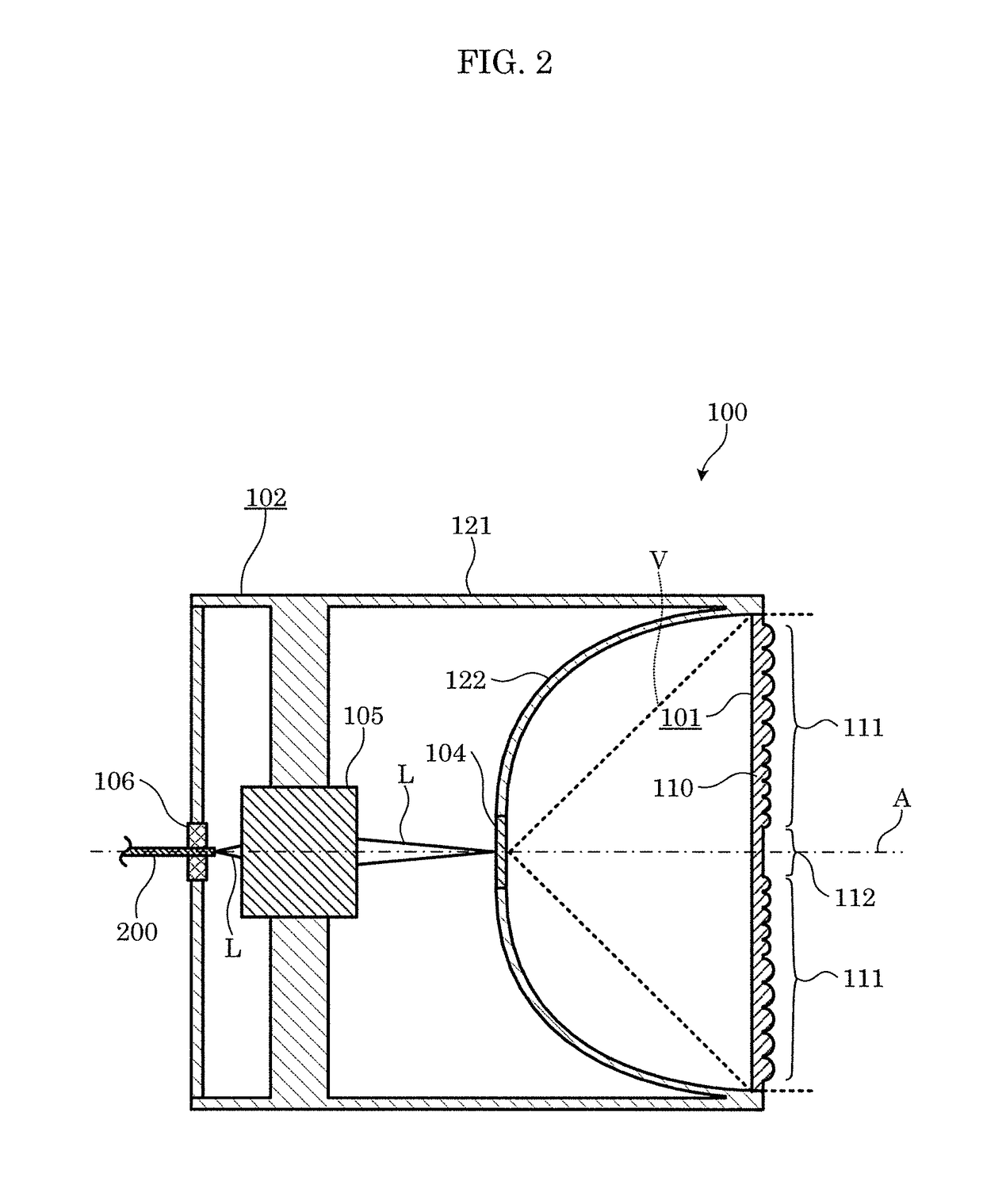
[0029]FIG. 2 is a cross-sectional view of the lighting apparatus.

[0030]As illustrated in these figures, lighting apparatus 100 is an apparatus that emits visible light, using laser light L as a light source, and includes light emitter 104 and cover 101. Furthermore, in this embodiment, lighting apparatus 100 includes case 102, optical system 105, and fiber attachment component 106.

[0031]As illustrated in FIG. 2, light emitter 104, when irradiated with laser light L, radiates light of a different wavelength, from laser light L, light emitter 104, for example, includes, in a dispersed state, phosphor particles which generate fluorescence when excited by laser light L, and irradiation with laser light L causes the phosphors to generate fluorescence that is of a different wavelength from laser light L...

Example

Embodiment 2

[0078]Next, another embodiment of lighting apparatus 100 will be described. It should be noted that the same reference sign is given to components (portions) having the same operation, function, shape, mechanism, or structure as in Embodiment 1, and their description may be omitted. Furthermore, hereinafter, description shall center on the points of difference from Embodiment 1, and there are instances where description of identical matter is omitted.

[0079]In lighting apparatus 100 according to Embodiment 2, the center coordinates (x, y) of each of small lenses 154 are disposed so as to satisfy subsequent Expressions (1) to (5).

[Math. 1]

O1−Dn≦2·d   Expression (1)

[0080]where

[0081]d is the radius of small lens 154 in a plan view (see FIG. 11)

[0082]n is the place in order, from origin O, of a virtual concentric circle (see FIG. 11)

[0083]Dn is the radius of nth virtual concentric circle from the origin (see FIG. 11)

[Math. 2]

O2·Dn·Π / d   Expression (2)

[0084]where

[0085]kn is th...

Example

Embodiment 3

[0092]Next, another embodiment of lighting apparatus 100 will be described. It should be noted that the same reference sign is given to components (portions) having the same operation, function, shape, mechanism, or structure as in Embodiments 1 and 2, and their description may be omitted. Furthermore, hereinafter, description shall center on the points of difference from Embodiments 1 and 2, and description of identical matter may be omitted.

[0093]In lighting apparatus 100 according to Embodiment 3, center C of each small lens 154 is placed on coordinates (x, y) which have been calculated to satisfy subsequent Expressions (6) to (8).

[Math. 6]

θn=360 / (6·n)   Expression (6)

[0094]where

[0095]n is the place in order, from the origin, of a virtual concentric circle D (see FIG. 11)

[0096]θn is the angle formed by the center of adjacent small lenses with respect to the origin (see FIG. 11)

[Math. 7]

x=√3d˜n·cos(θn·km+bn)   Expression (7)

[0097]where

[0098]d is the radius of one of th...


PUM


Abstract

A lighting apparatus which has a light emitter that emits light of a different wavelength from a laser light with which the lighting apparatus is irradiated is provided. The lighting apparatus includes a condenser lens that condenses the laser light, a focusing lens that focuses the laser light that has passed through the condenser lens, and an optical component disposed between the condenser lens and the focusing lens. The optical component includes a plurality of lenses disposed at a plurality of locations on circumferences of virtual concentric circles. The virtual concentric circles include a center which is an origin. Lenses which are adjacent along a radial axis passing through the origin, among the plurality of lenses, have different phases with respect to the radial axis.

Description

CROSS REFERENCE TO RELATED APPLICATION[0001]This application claims the benefit of priority of Japanese Patent Application Number 2015-204989 filed on Oct. 16, 2015, the entire content of which is hereby incorporated by reference.BACKGROUND[0002]1. Technical Field[0003]The present disclosure relates to a lighting apparatus which uses laser light as a light source.[0004]2. Description of the Related Art[0005]Conventionally, in a lighting apparatus, etc., there are instances where light, is not emitted evenly from the light exiting face, and unevenness such as illumination unevenness and color unevenness occurs in an irradiation region which is the region that is illuminated when an object is irradiated with light. Various devices and methods for reducing such unevenness have been proposed.[0006]For example, as a technique for reducing unevenness in the irradiation region, there is a known technique in which an optical component, which has a honeycomb structure of seamlessly arranged ...

Claims


Application Information

Patent Timeline
IPC IPC(8): F21V9/08F21V3/04F21V8/00F21V5/04F21V9/16
CPCF21V9/08F21V5/04F21Y2115/30G02B6/0008F21V3/04F21V9/16F21V5/008G02B3/0043G02B3/0056F21V9/30G02B3/00
Inventor NAKANO, YOSHIYUKI
Owner PANASONIC INTELLECTUAL PROPERTY MANAGEMENT CO LTD
Why Eureka
Try Eureka