Fixing structure and fixing method

a fixing structure and fixing method technology, applied in the direction of soldering apparatus, coupling device connection, manufacturing tools, etc., can solve the problem of difficulty in further and achieve the effect of reducing the irradiation time of laser beams per terminal

Active Publication Date: 2017-04-20
JAPAN AVIATION ELECTRONICS IND LTD
View PDF9 Cites 3 Cited by
  • Summary
  • Abstract
  • Description
  • Claims
  • Application Information

AI Technical Summary

Benefits of technology

[0012]According to the above-mentioned aspects of the present invention, the brazing filler metal enters the penetrating hole, thereby allowing the terminal to be fixed to the conductive pattern with the brazing filler metal disposed therebetween. Further, the fixation between the terminal and the brazing filler metal is not due to wetting phenomena. Accordingly, the laser beam irradiation time per terminal can be reduced as compared with a case where the fixation between the terminal and the brazing filler metal is due to wetting phenomena. Furthermore, according to the above-mentioned aspects of the present invention, since the brazing filler metal reaches the vicinity of the upper end of the penetrating hole, whether the terminal and the brazing filler metal are fixed to each other can be confirmed when a laser beam irradiation surface of the terminal is viewed from above.

Problems solved by technology

However, in the structure disclosed in Japanese Unexamined Patent Application Publication No. 2003-204149 described above, it has been difficult to further reduce the laser beam irradiation time per terminal.

Method used


Image

  • Fixing structure and fixing method
  • Fixing structure and fixing method
  • Fixing structure and fixing method

Examples


first exemplary embodiment

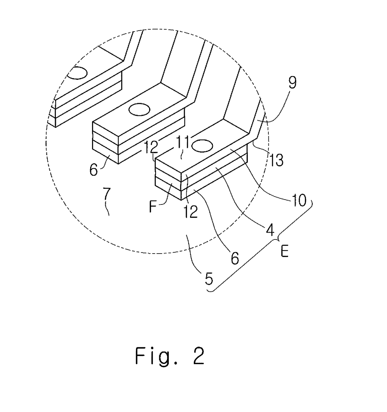
[0051]A first exemplary embodiment will be described below with reference to FIGS. 1 to 4.

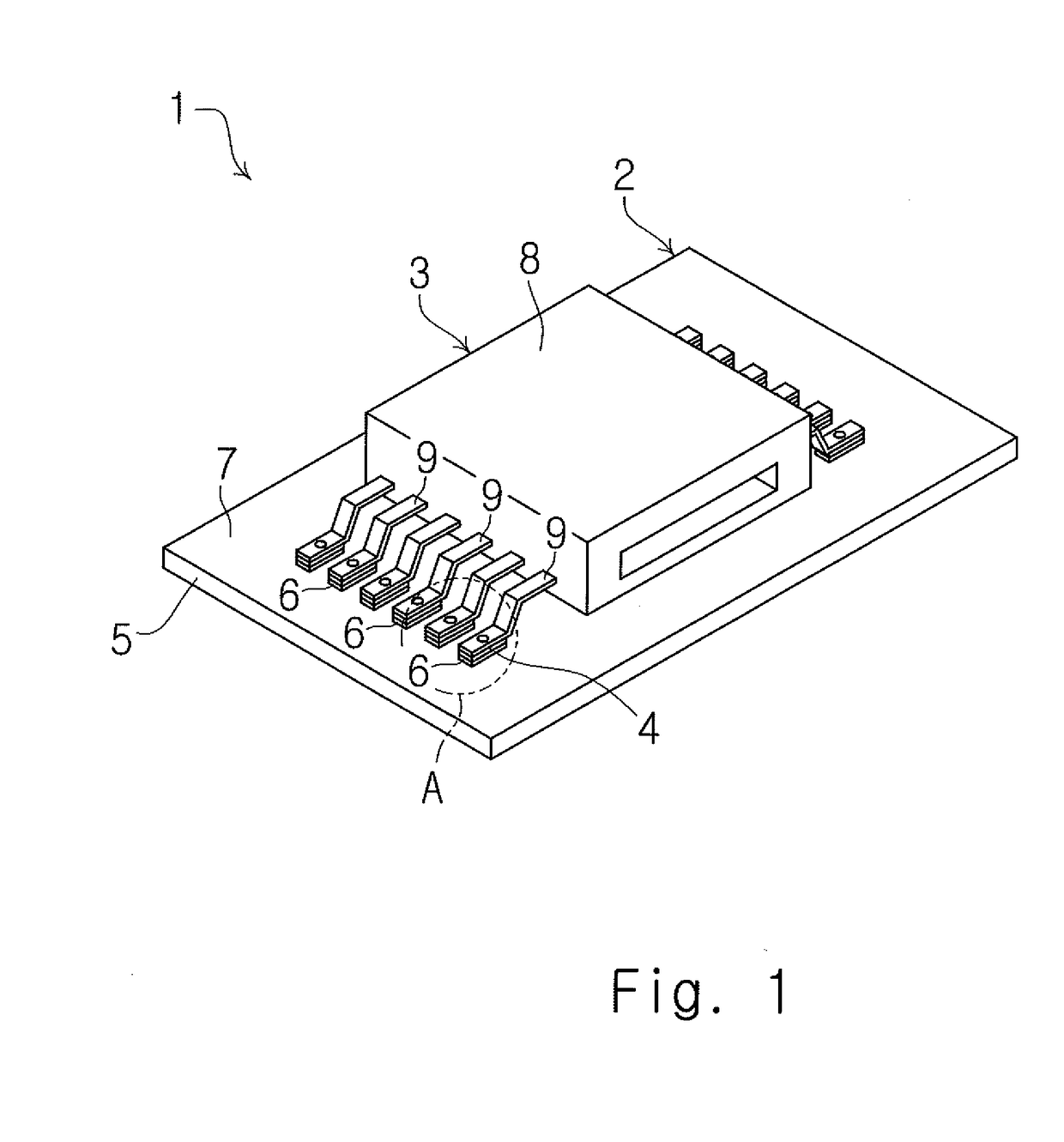
[0052]FIG. 1 is a perspective view of a circuit module 1. The circuit module 1 includes a circuit board 2, a connector 3 (electronic component), and an adhesive layer 4.

[0053]The circuit board 2 includes an insulating substrate (substrate) 5 and a plurality of conductive patterns 6. The insulating substrate 5 is formed of, for example, a glass epoxy resin or paper phenol. The plurality of conductive patterns 6 are formed on a connector mounting surface 7 of the insulating substrate 5. Each of the plurality of conductive patterns 6 is formed of, for example, a copper foil or aluminum foil.

[0054]The connector 3 includes a housing 8 and a plurality of terminals 9. The housing 8 is formed of an insulating resin. Each of the plurality of terminals 9 is formed of a Cu-based or Au-based metal. In the first exemplary embodiment, each of the plurality of terminals 9 is formed of a Cu-based metal and is ...

second exemplary embodiment

[0069]Next, a second exemplary embodiment will be described with reference to FIGS. 5 and 6. Differences between the first exemplary embodiment and the second embodiment will be mainly described, while a repeat of previous descriptions is omitted.

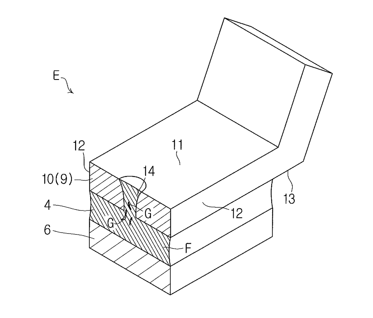
[0070]As shown in FIG. 3, in the first exemplary embodiment described above, the brazing filler metal F penetrates the terminal 9 and reaches the vicinity of the upper surface 11 of the fixed portion 10.

[0071]In contrast, in the second exemplary embodiment, as shown in FIGS. 5 and 6, the brazing filler metal F penetrates the terminal 9 and spreads over the upper surface 11 of the fixed portion 10 in a substantially circular shape. Specifically, as shown in FIG. 6, the brazing filler metal F spreads in a substantially circular shape to the outside of the upper opening 15 of the penetrating hole 14. The brazing filler metal F is deposited on the upper surface 11 of the fixed portion 10 at the outside of the upper opening 15 of the penetrating...

third exemplary embodiment

[0073]Next, a third exemplary embodiment will be described with reference to FIGS. 7 and 8. Differences between the first exemplary embodiment and the third embodiment will be mainly described, while a repeat of previous descriptions is omitted.

[0074]As shown in FIG. 3, in the first exemplary embodiment described above, the brazing filler metal F penetrates the terminal 9 and reaches the vicinity of the upper surface 11 of the fixed portion 10.

[0075]In contrast, in the third exemplary embodiment, as shown in FIGS. 7 and 8, the brazing filler metal F penetrates the terminal 9 and spreads over the upper surface 11 of the fixed portion 10 in a substantially circular shape. Specifically, as shown in FIG. 8, the brazing filler metal F spreads in a substantially circular shape to the outside of the upper opening 15 of the penetrating hole 14, and reaches the two side surfaces 12. The brazing filler metal F is deposited on the upper surface 11 and the two side surfaces 12 of the fixed port...


PUM

PropertyMeasurementUnit
zero cross timeaaaaaaaaaa
wavelengthaaaaaaaaaa

Abstract

A fixing method for fixing a terminal to a conductive pattern with a brazing filler metal disposed therebetween includes: a first step of disposing the brazing filler metal on the conductive pattern; a second step of bringing the terminal into contact with the brazing filler metal; and a third step of forming a penetrating hole in the terminal by irradiating a laser beam onto the terminal. In the third step, the laser beam is irradiated onto the terminal in such a manner that the penetrating hole is filled with the brazing filler metal melted by the irradiation of the laser beam.

Description

CROSS REFERENCE TO RELATED APPLICATIONS[0001]This application is based upon and claims the benefit of priority from Japanese patent application No. 2015-206109, filed on Oct. 20, 2015, the disclosure of which is incorporated herein in its entirety by reference.BACKGROUND OF THE INVENTION[0002]1. Field of the Invention[0003]The present invention relates to a fixing structure and a fixing method.[0004]2. Description of Related Art[0005]Japanese Unexamined Patent Application Publication No. 2003-204149 discloses a technique for soldering lead terminals 101 of an FPIC (Flat Package Integrated Circuit) 100 to a wiring electrode 103 of a printed board 102 as shown in FIG. 37 of the present application. Specifically, a laser beam 106 output from a laser oscillator 105 is irradiated onto each lead terminal 101, so that a solder layer 104 is melted and spread out and the lead terminal 101 is soldered to the wiring electrode 103.[0006]In particular, in the fields of FPIC and connectors, when ...

Claims


Application Information

Patent Timeline
Patent Type & Authority Applications(United States)
IPC IPC(8): H01R4/02B23K26/382H01R43/02B23K1/005
CPCH01R4/024B23K1/0056B23K2203/12H01R43/0221B23K2201/42B23K26/389H01R4/029H05K3/3494H05K2203/043B23K2101/42B23K1/005H01R13/03H01R13/405H01R43/0235H05K3/3421H05K3/3457H05K3/3489B23K2103/12
Inventor YOSHIDA, TAKUSHIAKIMOTO, HIROSHISEKI, YOSUKE
Owner JAPAN AVIATION ELECTRONICS IND LTD
Why Eureka
Try Eureka