
Sleeve tube and method of use

a sleeve tube and sleeve tube technology, applied in the field of sleeve tubes, can solve the problems of inability to adjust the curvature of the boehringer ingelheim tube, lack of sump channel, and risk of technical complications, so as to facilitate the insertion or withdrawal of the tube, improve patient outcomes, and reduce complications.

Inactive Publication Date: 2017-04-27
SASSE KENT C M D
View PDF0 Cites 4 Cited by
  • Summary
  • Abstract
  • Description
  • Claims
  • Application Information

AI Technical Summary

Benefits of technology

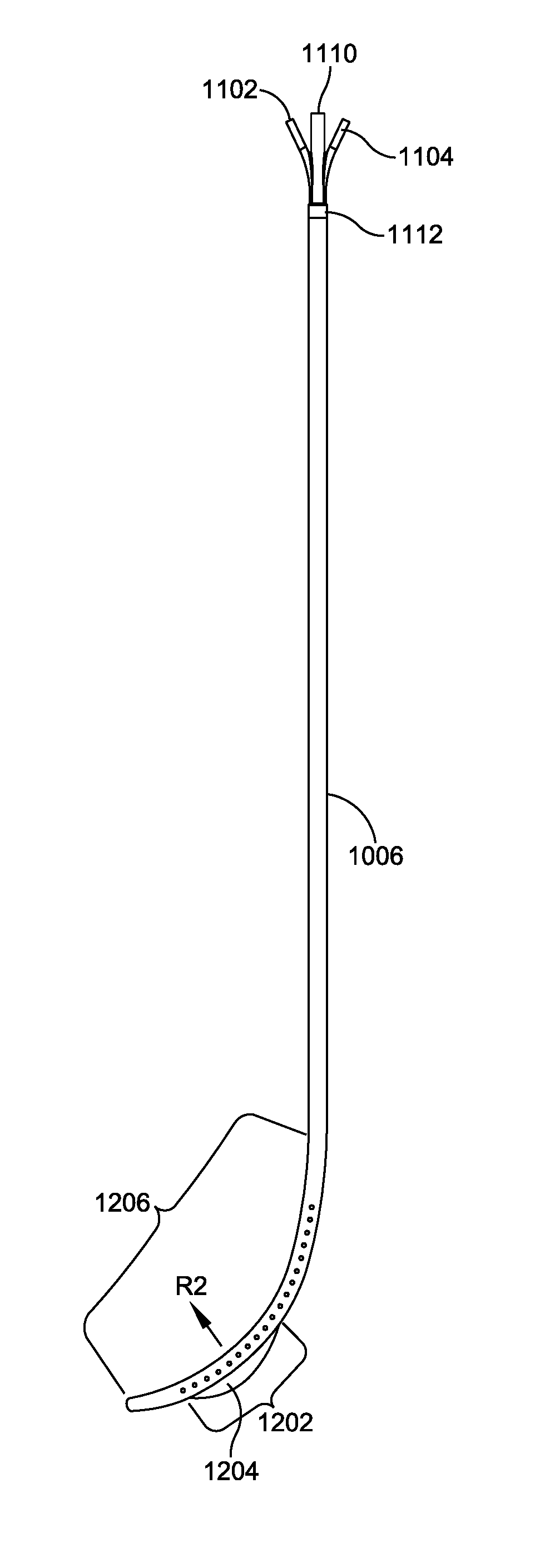
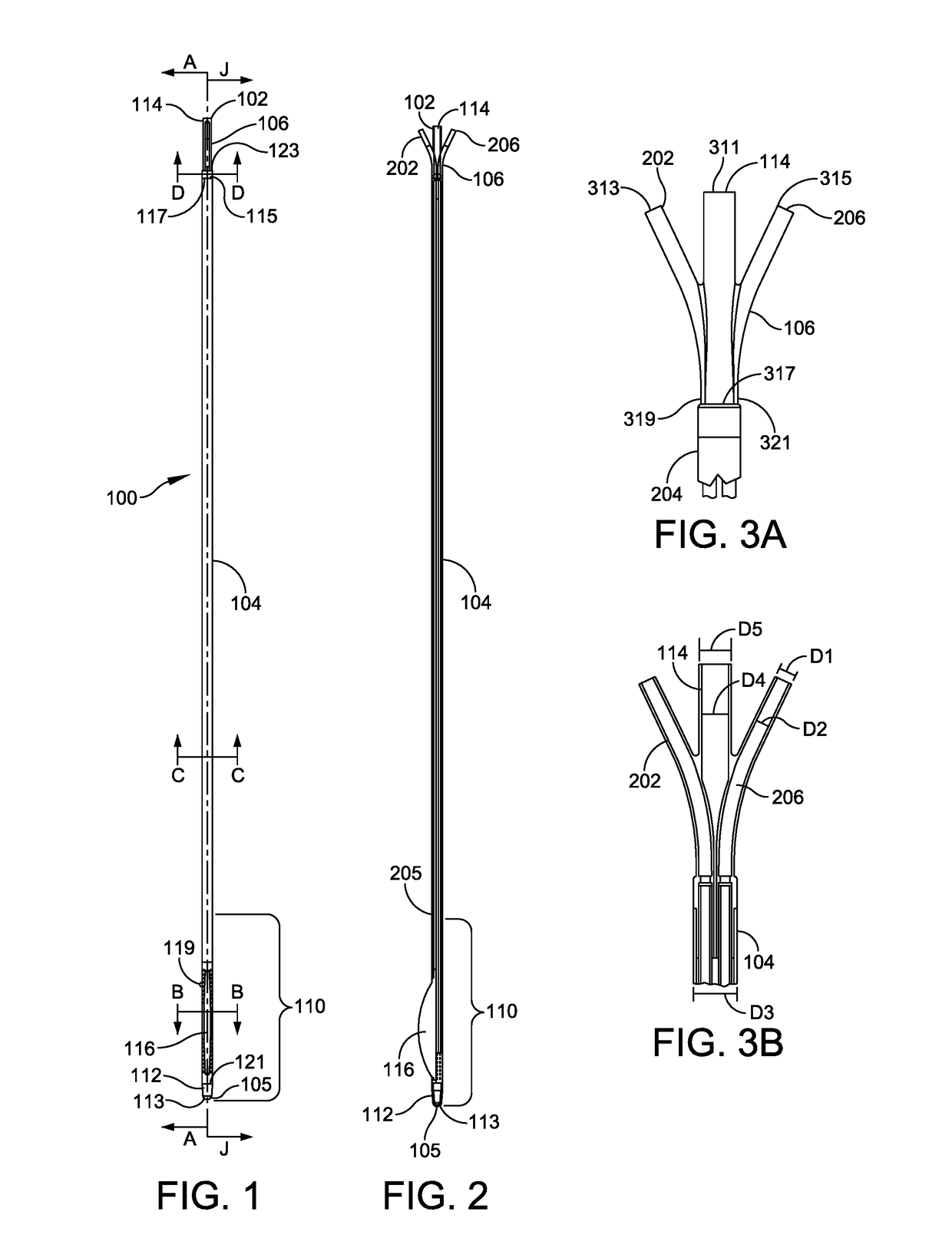
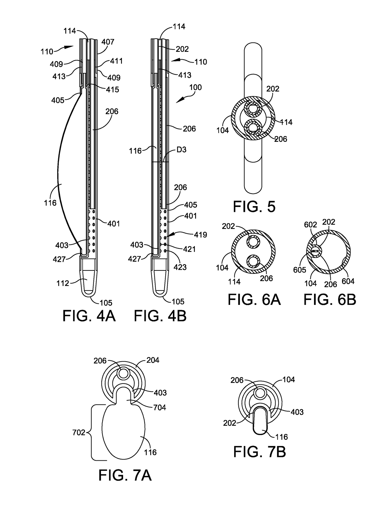
The invention is a sleeve tube that can perform multiple functions in a patient's esophagus. The multi-channeled tube eliminates the need for frequent tube placements and removals, reducing the risk of complications and cost savings. It also addresses post-operative narrowing by adding volume to the calibration tube to create additional space and prevent narrowing.

Problems solved by technology

Existing tube technology fails to conform to the curvature of the natural human stomach, and thus creates risks of technical complications in sleeve gastrectomy surgery—the existing tubes are typically straight, having no curvature and no way to make diameter adjustments at the incisura.
In addition, these tubes may be used for irrigation and / or as a sizing guide during surgery; however, the Boehringer Ingelheim tubes do not have adjustable curvature, lack a sump channel, and lack both a balloon channel and a balloon to augment the diameter at the incisura.
Furthermore, existing tube technology fails to suction, aspirate, and deflate the stomach adequately; commonly used prior art tubes either have no suction capabilities or the tubes use a simple, single-channel suction system that does not involve a sump, resulting in a system that can easily become clogged with gastric mucus or particulate matter.
In addition, existing technology may employ a tube having a blunt tip, where the tip is difficult to insert into the patient's stomach or results in anatomical trauma.
These cases are then typically treated with endoscopic dilatation procedures in the weeks and months following the initial surgery, at considerable expense.

Method used


Image

  • Sleeve tube and method of use
  • Sleeve tube and method of use
  • Sleeve tube and method of use

Examples


Embodiment Construction

[0047]The prior Brief Summary and the following description provide examples that are not limiting of the scope of this specification. One skilled in the art would recognize that changes can be made in the function and arrangement of elements discussed without departing from the spirit and scope of the disclosure. Various embodiments can omit, substitute, add, or mix and match various procedures or components as desired. For instance, the methods disclosed can be performed in an order different from that described, and various steps can be added, omitted, or combined. Also, features disclosed with respect to certain embodiments can be combined in or with other embodiments as well as features of other embodiments.

[0048]In an exemplary gastrectomy procedure, one embodiment of the sleeve tube includes each of a balloon channel, main channel, and sump channel extending from the proximal end of the sleeve tube to the working, distal section of the sleeve tube. The distal end of the sleev...


PUM


Abstract

Methods, systems, and devices are described for fabricating and using an orogatric tube. The orogastric tube may have: a proximal end section; a distal end section opposite the proximal end section, the distal end having a flexible, resilient curved portion; at least one sump channel extending from the proximal end section along a pre-determined length of the orogastric tube to the distal end section; at least one balloon channel extending from the proximal end section along a pre-determined length of the orogastric tube to the distal end section, the balloon channel being in communication with an expandable balloon in the distal end section; and a main channel enclosing a pre-determined length of both the sump channel and the balloon channel.

Description

CROSS-REFERENCE TO RELATED APPLICATIONS[0001]This application claims priority to, and incorporates by reference, the applicants' prior provisional patent application, titled Sleeve Tube and Method of Use, Ser. No. 62 / 245,542, filed Oct. 23, 2015.FIELD OF THE DISCLOSURE[0002]The present disclosure relates to an orogastric sleeve tube (“sleeve tube”) and methods of use, and in one aspect relates to a multi-channel sleeve tube that may be used in laparoscopic sleeve gastrectomy surgery. The sleeve tube may combine unique features of a gastric aspiration tube utilizing sump technology in combination with a novel sizing calibration tube.[0003]In some embodiments, the sleeve tube may be a calibration device to be used within the lumen of a patient's stomach, where the sleeve tube may be fabricated with a material or a combination of materials enabled to provide a modifiable curvature which can conform to the natural shape of the stomach. In other embodiments, sump aspiration may be enable...

Claims


Application Information

Patent Timeline
Patent Type & Authority Applications(United States)
IPC IPC(8): A61F5/00A61M1/00A61B5/00A61M25/10
CPCA61F5/0089A61M25/10A61M1/0039A61M2210/105A61M2205/0266A61M2210/1053A61B5/4238A61B2017/00725A61J15/0003A61B17/00234A61M2207/00A61B2017/00818A61M1/84A61M1/76
Inventor SASSE, KENT C.FISHER, MATTHEW T.
Owner SASSE KENT C M D
Learn More