
Guided thermal treatment system

a thermal treatment and guided technology, applied in the field of temperature control, can solve the problems of insufficient on-line monitoring of nf heating, inability to work in other tissue types, and insufficient mri temperature map information, so as to reduce unnecessary treatment delays, reduce the total cool-down period, and ensure treatment

Inactive Publication Date: 2017-04-27
KONINKLJIJKE PHILIPS NV
View PDF6 Cites 0 Cited by
  • Summary
  • Abstract
  • Description
  • Claims
  • Application Information

AI Technical Summary

Benefits of technology

The invention relates to a treatment protocol for preventing overheating and promoting efficient treatment. The technical effects of the invention include a more conservative heat accumulation algorithm that may prevent sonications even in the case of a small probability of adverse events, a mandatory part of the cool-down period to prevent overheating in non-sensitive patients, and a recommended part of the cool-down period to decrease treatment delays while ensuring safety.

Problems solved by technology

MRI temperature map information is, however, typically incomplete.
Furthermore, PRFS method works only in water containing tissues, and thus it typically gives information from the muscle, while the subcutaneous fat and skin (due to thin thickness) are not monitored.
Alternative T2 based methods can give information on the fat temperature, but this method does not work in other tissue types.
Consequently, sufficient on-line monitoring of NF heating is challenging, and typically calculation models are needed for safety algorithms.

Method used


Image

  • Guided thermal treatment system
  • Guided thermal treatment system
  • Guided thermal treatment system

Examples


Embodiment Construction

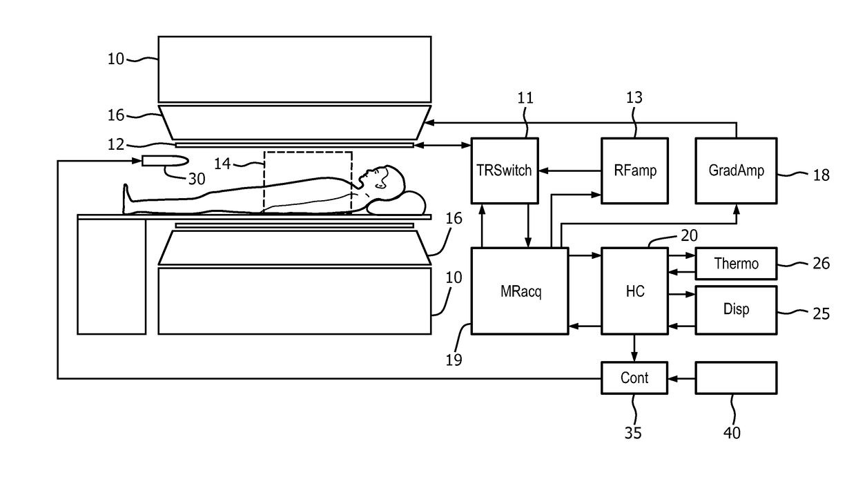
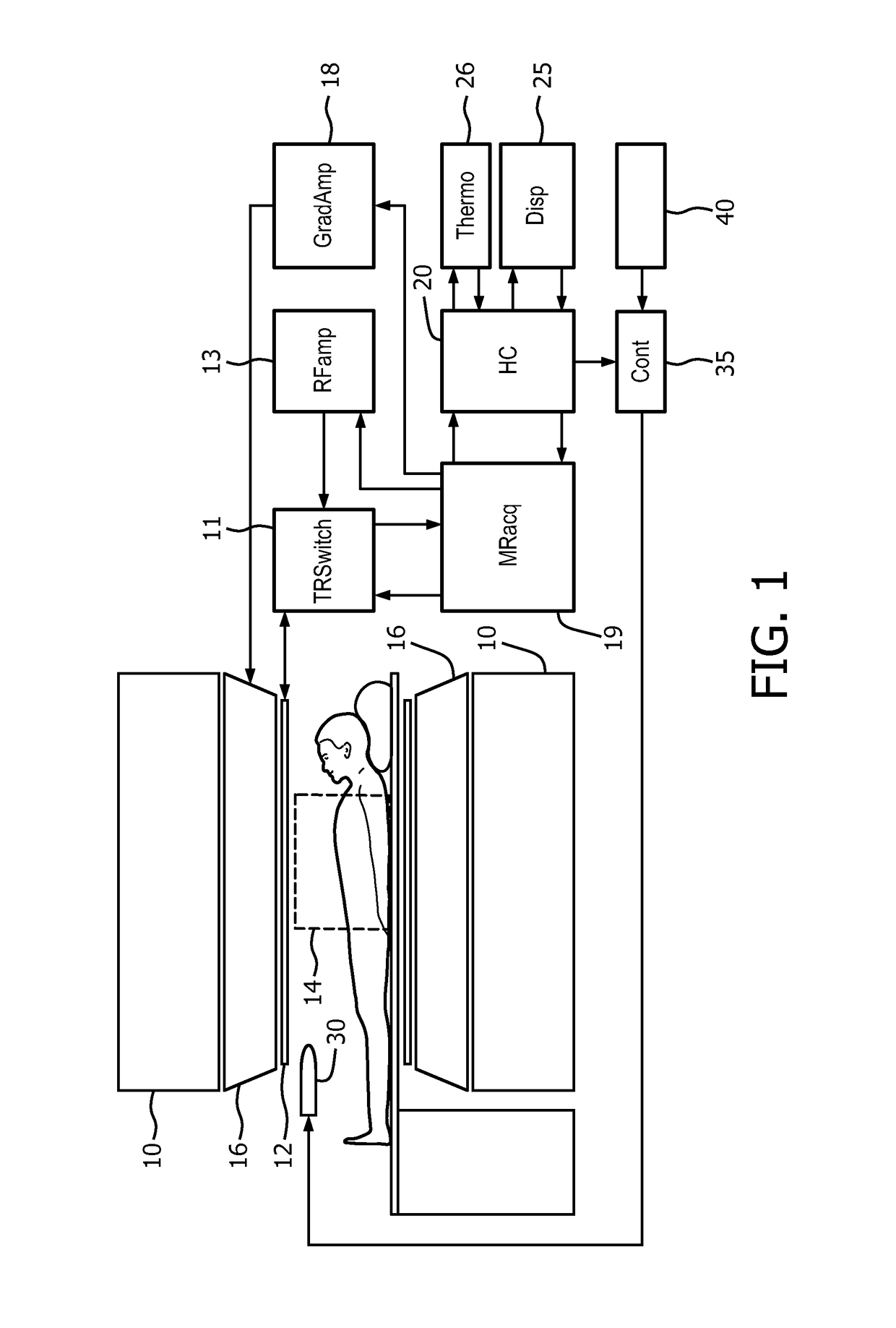
[0022]FIG. 1 illustrates diagrammatically an embodiment of a guided thermal treatment system in which the invention is used. The embodiment shown in FIG. 1 is an MR guided intervention system comprises a magnetic resonance system (not entirely shown) and a thermal therapy system 30. The invention is not limited to systems using MR for the guidance. Other technologies for guidance, wherein information about the temperature of the area exposed by the thermal pulses can be derived can be used. The thermal therapy system 30 could be anything used for MR guided thermal treatment. Thermal treatment could for example be applied by means of HIFU or by means of a microwave antenna. The thermal treatment system is configured for applying thermal treatment pulses, which are spaced by a cool-down period. The thermal treatment system can be turned on or off by a controller 35.

[0023]The magnetic resonance examination system comprises a main magnet 10 which generates a steady homogeneous main magn...


PUM


Abstract

It is an insight of the invention that to achieve good treatment efficiency there is a need to minimize the cooling times and while preventing overheating of a subject treated. This object is achieved by a guided thermal treatment system, comprising:—a thermal treatment system configured for applying thermal treatment pulses to a patient, wherein the thermal treatment pulses are spaced in time by a cool-down period,—a guidance system, configured to provide guidance to the thermal treatment, wherein the guidance system comprises a thermal module configured for providing a first and second level of cool-down period, the first level indicating a mandatory part of the cool-down period in which applying of a thermal treatment pulse is prohibited, the second level indicating a recommended part of the cool-down period in which applying a thermal treatment pulse would result in an elevated risk of overheating in a sensitive patient, but not in a non-sensitive patient.

Description

FIELD OF THE INVENTION[0001]The invention relates to a system in the field of guided thermal treatment and more specifically to the temperature control.BACKGROUND OF THE INVENTION[0002]In high-intensity focused ultrasound (HIFU) therapy ultrasound (US) focus is positioned within the target lesion to be heated. The aim is typically to ablate a lesion, but there are applications where non-ablative heating is enough.[0003]Typically a target is heated by applying thermal treatment pulse to it, whereby the target is exposed for a relative short time (order 10-100 s) to a high intensity ultrasound wave. This energy application is called sonication. Besides the heating of the target the ultrasound beam also heats tissues outside the target. Although the heating of a single sonication in the non-targeted area is typically too low to produce tissue damage, the heat accumulation of several sonications may cause safety issues. Typical adverse event of HIFU is skin burn in the area between US t...

Claims


Application Information

Patent Timeline
Patent Type & Authority Applications(United States)
IPC IPC(8): A61N7/02A61B34/20
CPCA61N7/02A61B2034/2051A61B34/20A61B18/1815A61B2018/00761A61B2034/104A61B2090/374A61B2018/00708A61B2034/252
Inventor TANTTU, JUKKA ILMARIYLIHAUTALA, MIKA PETRIKOSKELA, ILPO ASKO JULIUS
Owner KONINKLJIJKE PHILIPS NV
Learn More