Eureka AIR delivers breakthrough ideas for toughest innovation challenges, trusted by R&D personnel around the world.

Power nozzle repair with cooling hardware installed

Inactive Publication Date: 2017-05-04
GENERAL ELECTRIC CO
View PDF1 Cites 0 Cited by
  • Summary
  • Abstract
  • Description
  • Claims
  • Application Information

AI Technical Summary

Benefits of technology

The patent describes a method for treating turbine components by heating, welding, and annealing them at specific temperatures. This process allows for the installation of cooling hardware while reducing treatment cost and time. The technical effect of this method is to improve the quality and durability of gas turbine components.

Problems solved by technology

In some instances, the nozzles may develop cracks and / or other surface discontinuities during operation that may require periodic repair via, e.g., welding.
This is a time-consuming and expensive process.

Method used


Image

  • Power nozzle repair with cooling hardware installed
  • Power nozzle repair with cooling hardware installed
  • Power nozzle repair with cooling hardware installed

Examples


Embodiment Construction

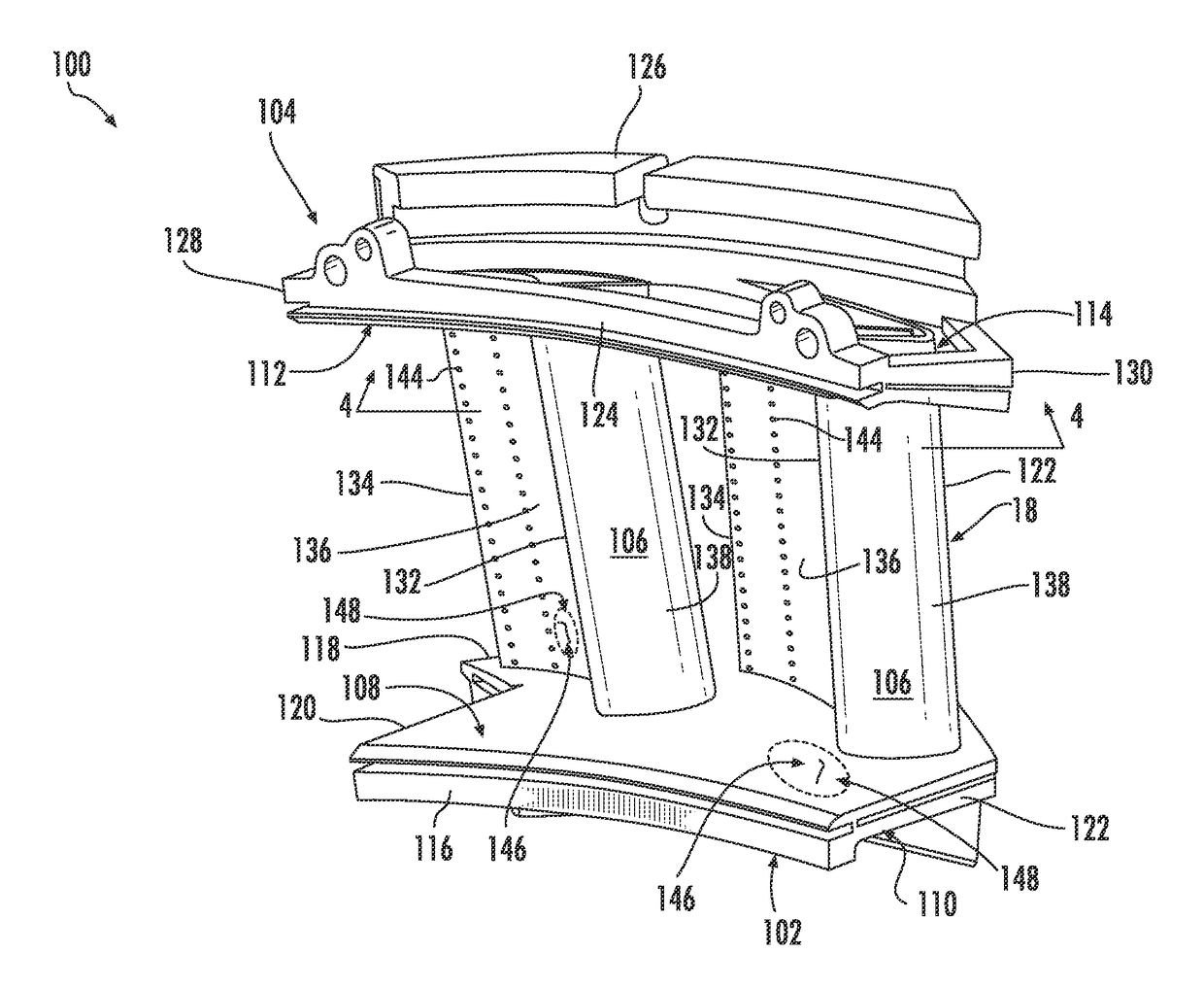
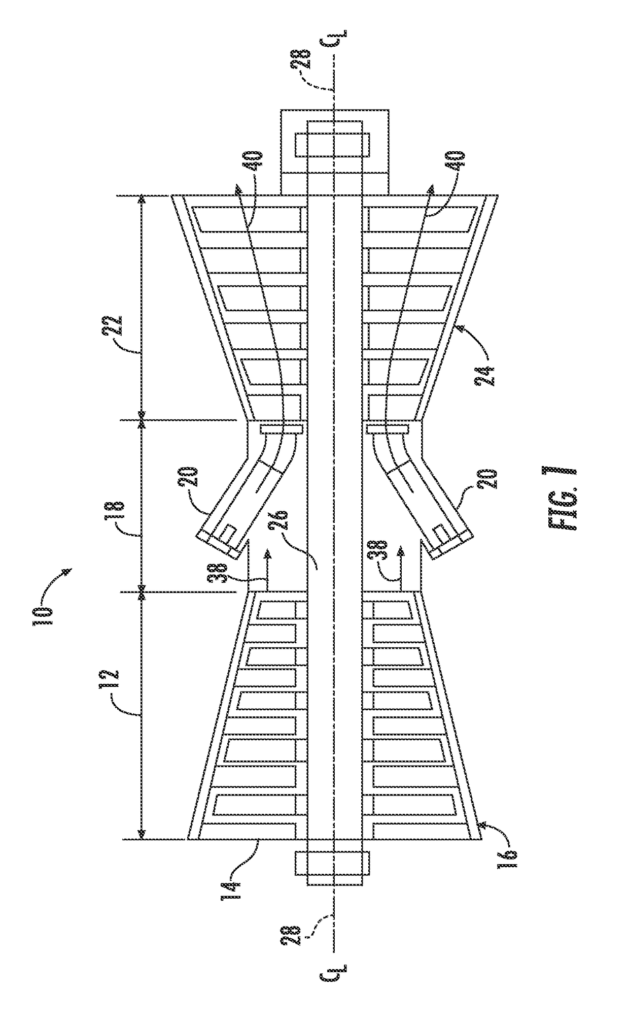
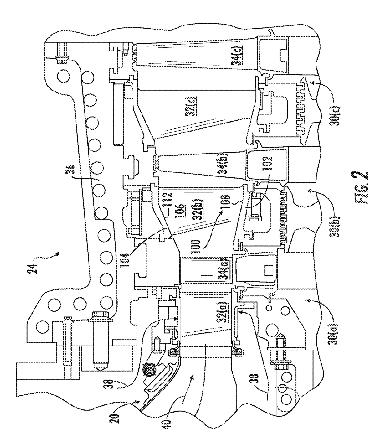
[0016]Reference will now be made in detail to present embodiments of the invention, one or more examples of which are illustrated in the accompanying drawings. The detailed description uses numerical and letter designations to refer to features in the drawings. Like or similar designations in the drawings and description have been used to refer to like or similar parts of the invention.

[0017]As used herein, the terms “first”, “second”, and “third” may be used interchangeably to distinguish one component from another and are not intended to signify location or importance of the individual components. The terms “upstream” and “downstream” refer to the relative direction with respect to fluid flow in a fluid pathway. For example, “upstream” refers to the direction from which the fluid flows, and “downstream” refers to the direction to which the fluid flows. The term “radially” refers to the relative direction that is substantially perpendicular to an axial centerline of a particular co...


PUM

PropertyMeasurementUnit
Temperatureaaaaaaaaaa

Abstract

In one aspect, the present disclosure is directed to a method for treating a region of a gas turbine component. The method includes heating the region to a first temperature. One or more surface discontinuities located in the region are welded such that at least a portion of the region is heated to a second temperature. The region is annealed at a third temperature. The second temperature is relatively greater than the first temperature, and the first temperature is relatively greater than the third temperature.

Description

FIELD OF THE INVENTION[0001]The present disclosure generally relates to a gas turbine and, more particularly, to a method for treating or repairing a gas turbine component.BACKGROUND OF THE INVENTION[0002]A gas turbine generally includes a compressor section, a combustion section, and a turbine section. The compressor section progressively increases the pressure of a working fluid entering the gas turbine and supplies this compressed working fluid to the combustion section. The compressed working fluid and a fuel (e.g., natural gas) mix within the combustion section and burn in a combustion chamber to generate high pressure and high temperature combustion gases. The combustion gases flow from the combustion section into the turbine section where they expand to produce work. For example, expansion of the combustion gases in the turbine section may rotate a shaft connected, e.g., to a generator to produce electricity. The combustion gases then exit the gas turbine via an exhaust secti...

Claims


Application Information

Patent Timeline
IPC IPC(8): B23P6/00F01D25/00C22F1/10B23K9/173B23K26/34B23K31/02F01D9/02B23K15/00
CPCB23P6/002F01D9/02F01D25/005B23K15/0093B23K15/0086B23K9/173B23K2203/08B23K31/02C22F1/10F05D2220/32F05D2230/232F05D2230/41B23K2201/001B23K26/34B23P6/045B23K9/044B23K9/167B23K2101/001B23K2103/26C21D9/50F01D5/005B23K2103/08
Inventor JOHNSON, JR., JERE ALLENZHANG, LIMINGLUSBY, CURTIS JOSEPH
Owner GENERAL ELECTRIC CO
Why Eureka
Eureka Blog
Learn More