Eureka AIR delivers breakthrough ideas for toughest innovation challenges, trusted by R&D personnel around the world.

Powering an esp sensor using ac current

Active Publication Date: 2017-05-04
RMS PUMPTOOLS LTD
View PDF1 Cites 1 Cited by
  • Summary
  • Abstract
  • Description
  • Claims
  • Application Information

AI Technical Summary

Benefits of technology

This patent describes a new system that eliminates a filter used in existing systems, allowing for better power transfer to remote equipment. Additionally, the system can carry both power and communication currents in the same phase-loop, eliminating the need for separate ground-return currents. These technical effects result in higher power transfer and more efficient communication.

Problems solved by technology

A limitation of known power-line communication systems is that they have a low power transfer capability.
Another limitation is the adverse effect of system grounding. FIG. 5 shows a fault at the bottom of the phase A winding of the motor.
This presents a short circuit across the remote inductor-capacitor filter and it becomes impossible to transfer power to the remote device.
Yet another limitation is the bandwidth achievable for data communications.
As a result, they do not have the capacity to pass high frequency signals and the bandwidth is limited to around 5-10 bits-per-second.
A further limitation is that it is difficult to deploy more than one loop-powered transmitter in parallel within the system.
This is because if one transmitter fails by shorting to ground then all the transmitters will fail.
Also if one transmitter fails by not maintaining a stable current when it is not communicating then this affects all the transmitters.
Furthermore, a time-division-multiplex scheme needs implemented between the multiple transmitters and this reduces the bandwidth per device from what is already a low capacity.
This becomes impractical due to the need to pass these multiple currents through the inductor ZL1.

Method used


Image

  • Powering an esp sensor using ac current
  • Powering an esp sensor using ac current
  • Powering an esp sensor using ac current

Examples


Embodiment Construction

[0033]FIG. 6 shows an isolated electrical submersible power system. The power system has three phases: phase A, phase B and phase C. A three phase isolating step up transformer is connected via a three phase cable to a three phase electrical submersible power motor. The system is designed such that, in use, the step up transformer is located above ground and the motor operates down-hole, below ground.

[0034]The step up transformer is represented in FIG. 6 by a neutral point 10 and three secondary windings 12. Each secondary transformer winding 12 has one terminal connected to the transformer neutral point 10 to form a star or wye configuration and a second terminal connected to a phase of the ESP cable.

[0035]The ESP motor is represented by three ESP motor windings 14 and an ESP motor neutral point 16. All three phases of the ESP cable extend down-hole and are connected to the three windings 14 of the ESP motor. This arrangement allows each winding 14 of the motor to be driven by alte...


PUM


Abstract

A system for powering down-hole instrumentation / equipment used with an electrical submersible pump that has a motor and a cable, the system comprising a down-hole current transformer operable to convert a current in a phase of the cable to power down-hole instrumentation.

Description

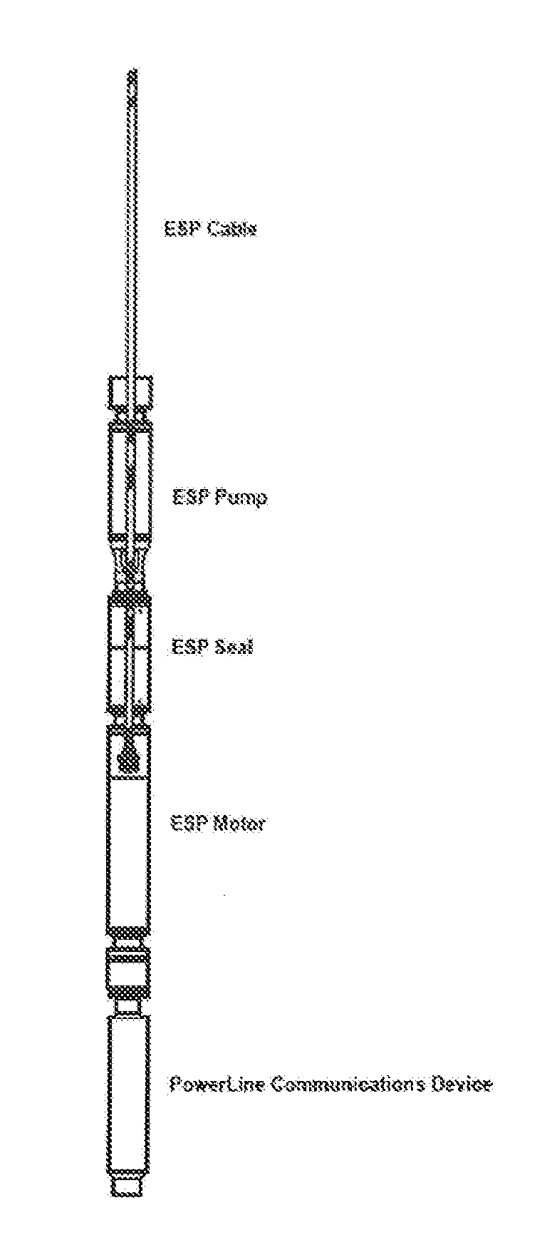
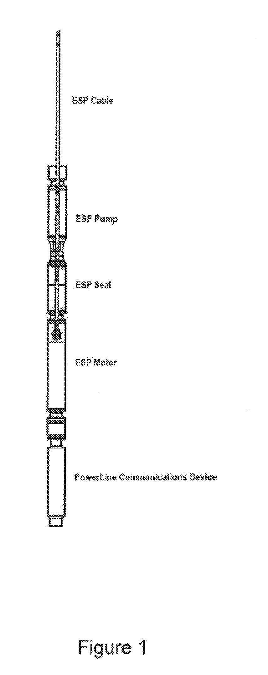
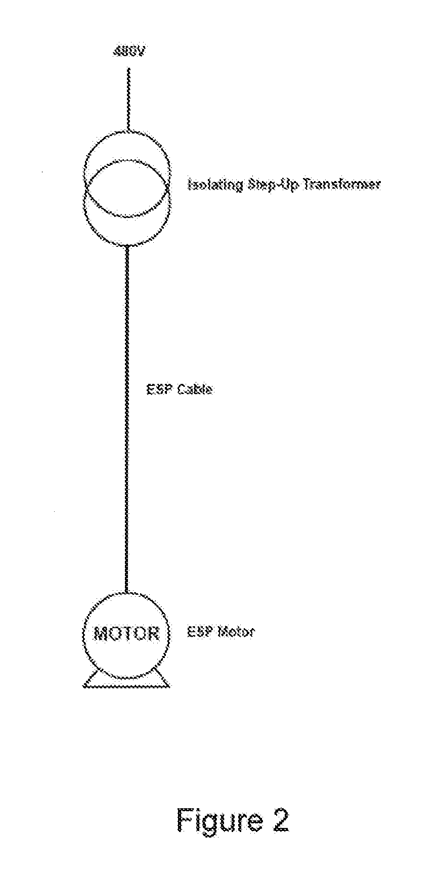
CROSS-REFERENCE TO RELATED APPLICATION[0001]This application claims priority to and the benefit of United Kingdom Patent Application No. 1519140.6, filed on Oct. 29, 2015, the contents of which as are incorporated by reference herein in their entirety.BACKGROUND[0002]Related Field[0003]The present invention relates to an electric submersible pump system. In particular, the present invention relates to a power supply for use with an electric submersible pump system. The power supply can be used to power down-hole electronics, for example down-hole communication systems.[0004]FIG. 1 shows a typical oil-well electric submersible pump (ESP) system. This has a down-hole three phase cable, a three phase ESP motor, an ESP seal section (an oil reservoir and bearing assembly), an ESP pump and a remote electronic instrumentation system with power-line communications capability. FIG. 2 shows a single-line diagram for the system of FIG. 1. This has a 480V AC supply, a multi-tapped, step-up isol...

Claims


Application Information

Patent Timeline
IPC IPC(8): E21B41/00H04B3/54
CPCE21B41/00E21B43/128H04B3/54Y04S40/121Y02B90/20Y04S40/124E21B47/12H02J13/00009E21B47/13H02J13/00016
Inventor ROBERTSON, MARK PATRICK
Owner RMS PUMPTOOLS LTD
Why Eureka
Eureka Blog
Learn More