

Multi-beam resonance light energy-carrying communication system
An energy-carrying communication and resonant light technology, applied in transmission systems, electromagnetic wave transmission systems, electromagnetic transmitters, etc., can solve the problems of inability to supply mobile power for a large number of mobile devices, and inability to provide consumers with a Wi-Fi-like mobile charging experience, etc. Satisfy the effects of high-power energy transfer and high-bandwidth communication, expanding capacity, and increasing system capacity
- Summary
- Abstract
- Description
- Claims
- Application Information
AI Technical Summary
Problems solved by technology
Method used
Image

Examples
Embodiment 1
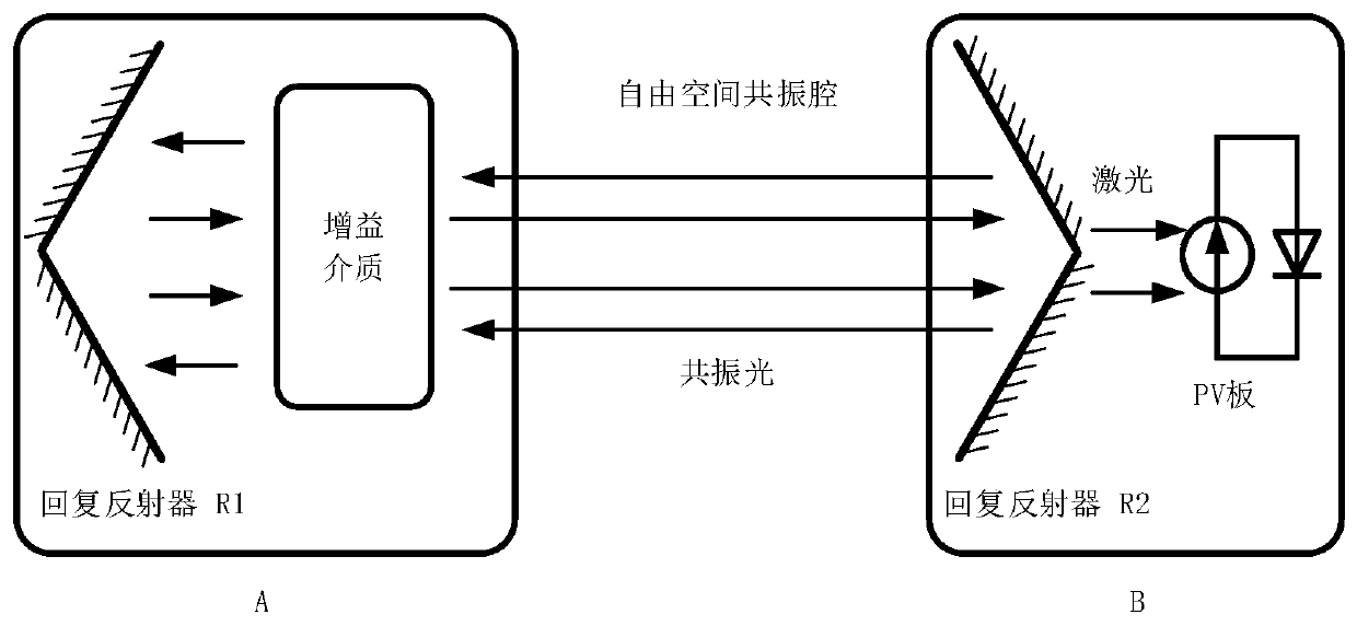
[0032] As a way of energy propagation, light waves can realize safe, long-distance, and mobile wireless energy transmission; at the same time, as a way of information transmission, light waves can realize wireless energy carrying communication (Simultaneous Wireless Information and Power Transfer, SWIPT). In a distributed optical resonant structure based on a single beam of light, the transmitter A and receiver B are spatially independent, the transmitter A includes a gain medium and a retro-reflective structure R1, and the receiver B includes a retro-reflective structure R2 and an optoelectronic Converted PV panels such as figure 1 shown.
[0033] Retro-reflectors R1 and R2 in receiver B can reflect the incident light back the same way. When the gain medium is excited to generate a photon beam, the photon beam will oscillate back and forth between the retro-reflectors R1 and R2 to form a stable resonant beam. The retro-reflector R1 can be a total reflection structure, and R...
Embodiment 2
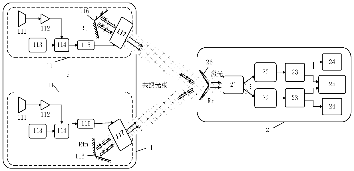
[0044] This embodiment provides a multi-beam resonant light energy-carrying communication system. The structure of the system is basically the same as that of the multi-beam resonant light energy-carrying communication system described in Embodiment 1, except that:
[0045] The light emitted by each resonant light sending module 11 can be directly sent out and can be synthesized into a beam of light by the laser beam combiner 118 for sending.
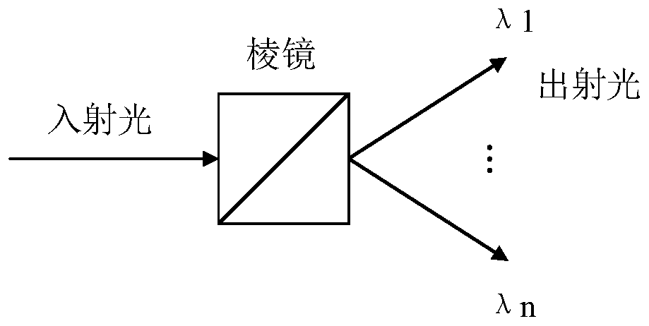
[0046] In each resonant light sending module 11 , the frequency component of the resonant light excited by the gain medium 117 is single, and multiple beams of light generated by each module can be integrated into one beam of light through the beam combiner 118 to be emitted. Such as Figure 6 As shown, the beam combiner 118 is arranged at the transmitting intersection end of the transmitting antenna 116 of each resonant optical transmitting module 11 . The incident light of each single frequency component passes through the prism and ...
PUM
 Abstract
Description
Claims
Application Information