Test jig for coating adhesion strength

a technology of adhesion strength and test jig, which is applied in the direction of measurement devices, instruments, scientific instruments, etc., can solve the problems of lowering the reliability of the test, labor may be cut, and the process of cutting a grid pattern on the coating relies on labor, so as to accurately measure the adhesion strength of the coating

Active Publication Date: 2017-05-04
HUANWEI ELECTRONICS SHANGHAI CO LTD
View PDF7 Cites 13 Cited by
  • Summary
  • Abstract
  • Description
  • Claims
  • Application Information

AI Technical Summary

Benefits of technology

[0006]The present invention has been accomplished under the circumstances in view. It is an objective of the present invention to provide a test jig for coating adhesion strength, which can accurately measure the adhesion strength of the coating on the test sample.

Problems solved by technology

Conventionally, the procedure of cutting a grid pattern on the coating relies on labors.
This test method usually has the following drawbacks: (1) It is difficult to precisely control the cutting angle, the cutting pressure and the cutting velocity of the cutting knife in cutting the surface of the coating, and thus, the cutting result is usually lack of consistency, lowering the reliability of the test result;(2) This manual cutting procedure is not applicable to a sample with its surface area smaller than 1 cm2, or a sample having an uneven surface;(3) The labor may be cut accidentally.

Method used


Image

  • Test jig for coating adhesion strength
  • Test jig for coating adhesion strength
  • Test jig for coating adhesion strength

Examples


Embodiment Construction

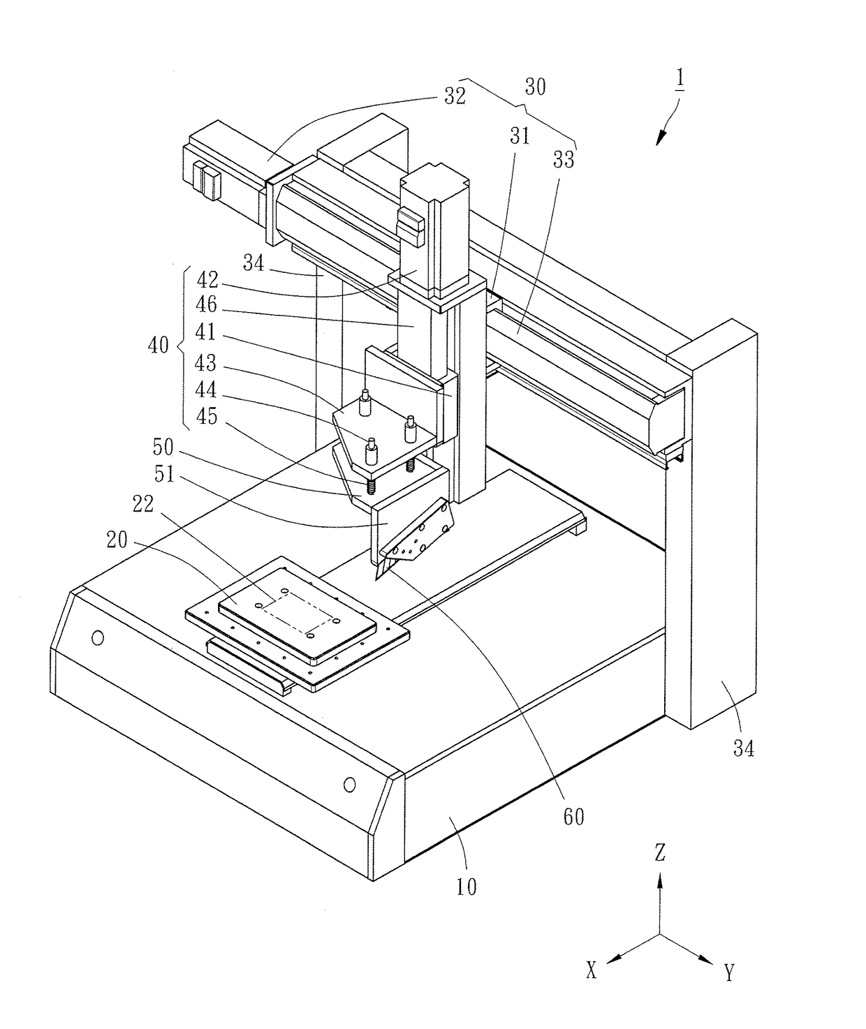
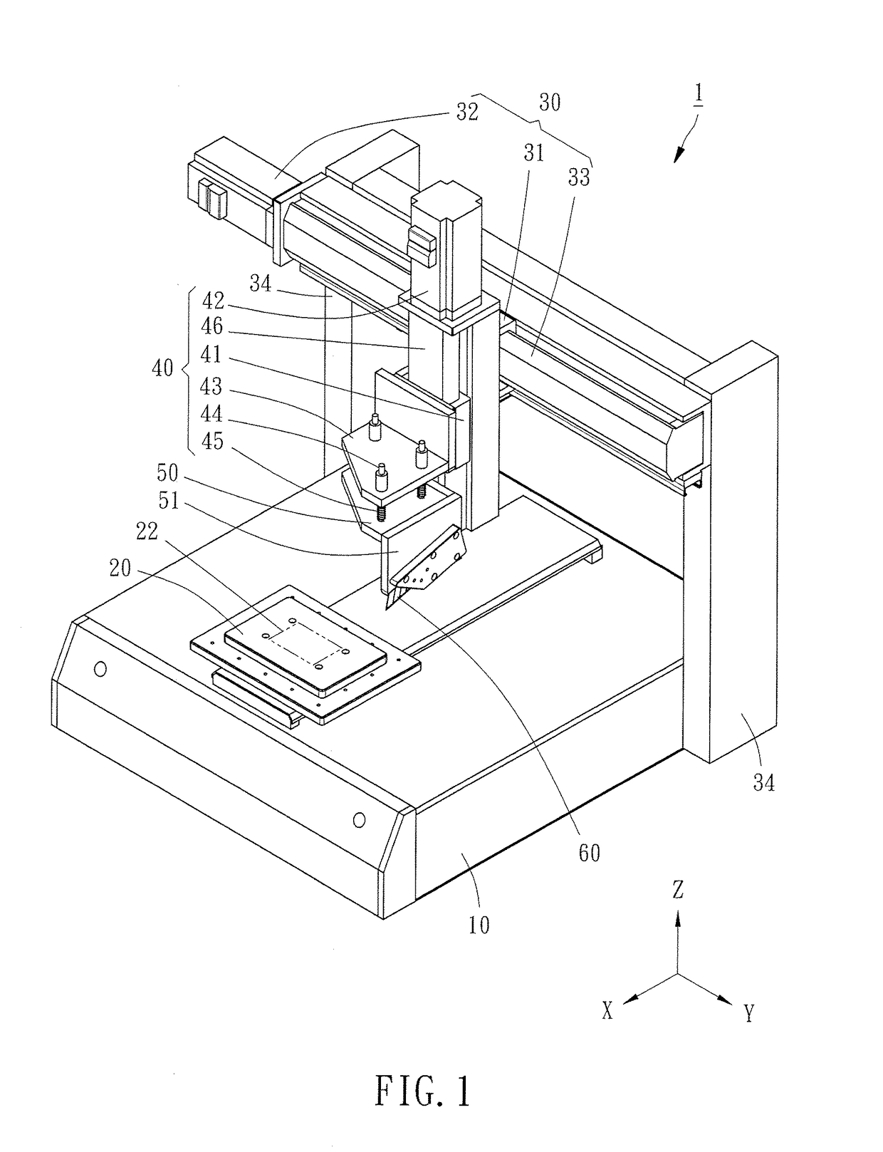
[0018]Referring to FIGS. 1-3, to facilitate explanation of an embodiment of the present invention, a first direction, a second direction and a third direction hereinafter described are respectively referred to X-axis direction, Y-axis direction and Z-axis direction of a Cartesian coordinate system, wherein the first direction, the second direction and the third direction are respectively disposed perpendicular to one another, however, the first, second and third directions described in the present preferred embodiment are not limited to the aforesaid Cartesian coordinate system.

[0019]The coating adhesion strength test jig 1 comprises a base 10, a sample carrier 20, a first displacement mechanism 30, a second displacement mechanism 40, a cutting knife holder 50, two cutting knives 60 and a controller (not shown). The structure of these components parts and their relationship are described hereinafter.

[0020]Referring first to FIG. 1, the sample carrier 20 is mounted on the base 10. Th...


PUM

PropertyMeasurementUnit
contained angleaaaaaaaaaa
surface areaaaaaaaaaaa
contained angleaaaaaaaaaa

Abstract

A test jig for coating adhesion strength includes a base, a sample carrier, a first displacement mechanism and a second displacement mechanism mounted on the base, and a cutting knife holder equipped with two differently oriented cutting knives that is mounted between the second displacement mechanism and the sample carrier. The sample carrier, the first displacement mechanism and the second displacement mechanism can be driven to move such that the cutting knives can exert a constant pressure to cut the sample on the sample carrier.

Description

BACKGROUND OF THE INVENTION[0001]1. Field of the Invention[0002]The present invention relates to coating adhesion strength test technology, and more particularly, to a coating adhesion strength test jig that can automatically and accurately test the coating adhesion strength of a sample.[0003]2. Description of the Related Art[0004]Conventionally, the test method for evaluating the coating adhesion strength is described as follows. Using a specific cutting knife to cut a grid pattern on the surface of the coating, adhering an adhesive tape to the grid pattern and removing the adhesive tape from the grid pattern. Then, evaluating the coating adhesion strength by checking the peeling status. Normally, coating adhesion strength can be classified into the following six grades:Class.543210PeelingNoPeel-offPeel-off areaPeel-offPeel-offPeel-offstatuspeelingarea <5%within 5-15%area withinarea withinarea15-35%35-65%>65%[0005]Conventionally, the procedure of cutting a grid pattern on the...

Claims


Application Information

Patent Timeline
Patent Type & Authority Applications(United States)
IPC IPC(8): G01N19/04
CPCG01N19/04G01N35/0099G01N2203/0091
Inventor YEH, CHIH-KAOSHAO, XIAO-LI
Owner HUANWEI ELECTRONICS SHANGHAI CO LTD
Why Eureka
Try Eureka