Organic electroluminescent module, smart device, and illumination apparatus

a technology of electroluminescent modules and smart devices, applied in the direction of instruments, computing, electric digital data processing, etc., can solve the problems of affecting the detection of the variation of capacitance in the surface capacitive scheme, increasing the thickness of the device, increasing the production steps, etc., to prevent the error of touch sensing in the touch function, small thickness, and small format

Inactive Publication Date: 2017-05-04
KONICA MINOLTA INC
View PDF3 Cites 17 Cited by
  • Summary
  • Abstract
  • Description
  • Claims
  • Application Information

AI Technical Summary

Benefits of technology

[0035]The above-described embodiments of the present invention can provide a specific organic electroluminescent module enabling to prevent error touch sensing in touch function between a plurality of organic electroluminescent elements, with achieving a small format and a small thickness, and simplified process, and to provide a smart device and an illumination apparatus provided with this organic electroluminescent module. The specific organic electroluminescent module has an organic electroluminescent panel including a plurality of organic electroluminescent elements laid out in series provided with an electrode used for both a light-emission function and a touch-sensing function, and a specific control circuit.
[0036]The technical features and mechanism to provide advantageous effects of the organic electroluminescent module defined in the present invention will now be described.
[0037]A conventional organic electroluminescent module applied to an icon region of a smart medium includes an organic electroluminescent panel including paired opposite electrodes and a touch sensing electrode for detecting a touch, such as a flexible printed circuit (FPC). In such a conventional organic electroluminescent module, a light-emitting function and a touch sensing function are provided by different assemblies. The conventional organic electroluminescent module having such a configuration inevitably has a large thickness, which hinders a reduction in sizes of an organic electroluminescent element.
[0038]To address the problem, the present inventors have proposed the following organic electroluminescent module (hereinafter simply referred to as “organic EL module”). The proposed module contains an organic electroluminescent panel (hereinafter simply referred to as “organic EL panel”) contains an organic electroluminescent element (hereinafter simply referred to as “organic EL element”) including a first electric controller and a second electric controller. The first electric controller is a light-emitting device driving circuit unit that is disposed between the paired opposite electrodes and is configured to control light emission. The second electric controller is a touch sensing circuit unit to cause at least one of the paired electrodes to function as a touch sensing electrode.
[0039]As describe above, an anode or a cathode is usually set as a touch sensing electrode (hereinafter simply referred to as “sensing electrode”) in an organic EL panel or organic EL element, where Cf is a finger capacitance between the finger and the touch sensing electrode, and Cel is an interelectrode capacitance between the anode and the cathode. In this state, the capacitance between the anode and the cathode is “Cf+Cel” at a touch (finger-touch) and is Cel at no finger-touch. The interelectrode capacitance Cel is greater than the finger capacitance Cf in general organic EL panels or organic EL element (Cf<Cel). Such relation precludes touch detection.
[0040]In the above-described proposed organic EL module, the light-emitting device driving circuit unit and the touch sensing circuit unit are separately provided. In addition, at a touch detection, the switches between the anode and the cathode and the light-emitting device driving circuit section are turned off and at least one of the anode and the cathode, or both of them are in a floating potential so that the interelectrode capacitance Cel between the anode and the cathode is not detected. This configuration can provide a touch sensing function and can contribute to reductions in sizes and thickness and simplified production steps of the organic electroluminescent device.

Problems solved by technology

Particularly, in a surface emission organic electroluminescent device, an anode, a cathode, or a metal foil protective layer, which is a composing member of an organic electroluminescent device, adversely affects the detection of the variation of the capacitance in the surface capacitive scheme.
In use of such assembly, a device for detecting the touch, such as an FPC, should be additionally prepared, resulting in several disadvantages, such as increased costs, increased thicknesses of the devices, and increased production steps.
It was found out that there was produced a problem that other organic EL element received touch information when one organic EL element was touched with a finger to result in causing error sensing.
This becomes a serious obstacle for making a configuration of a plurality of organic EL elements laid out in series.

Method used


Image

  • Organic electroluminescent module, smart device, and illumination apparatus
  • Organic electroluminescent module, smart device, and illumination apparatus
  • Organic electroluminescent module, smart device, and illumination apparatus

Examples


embodiment 1

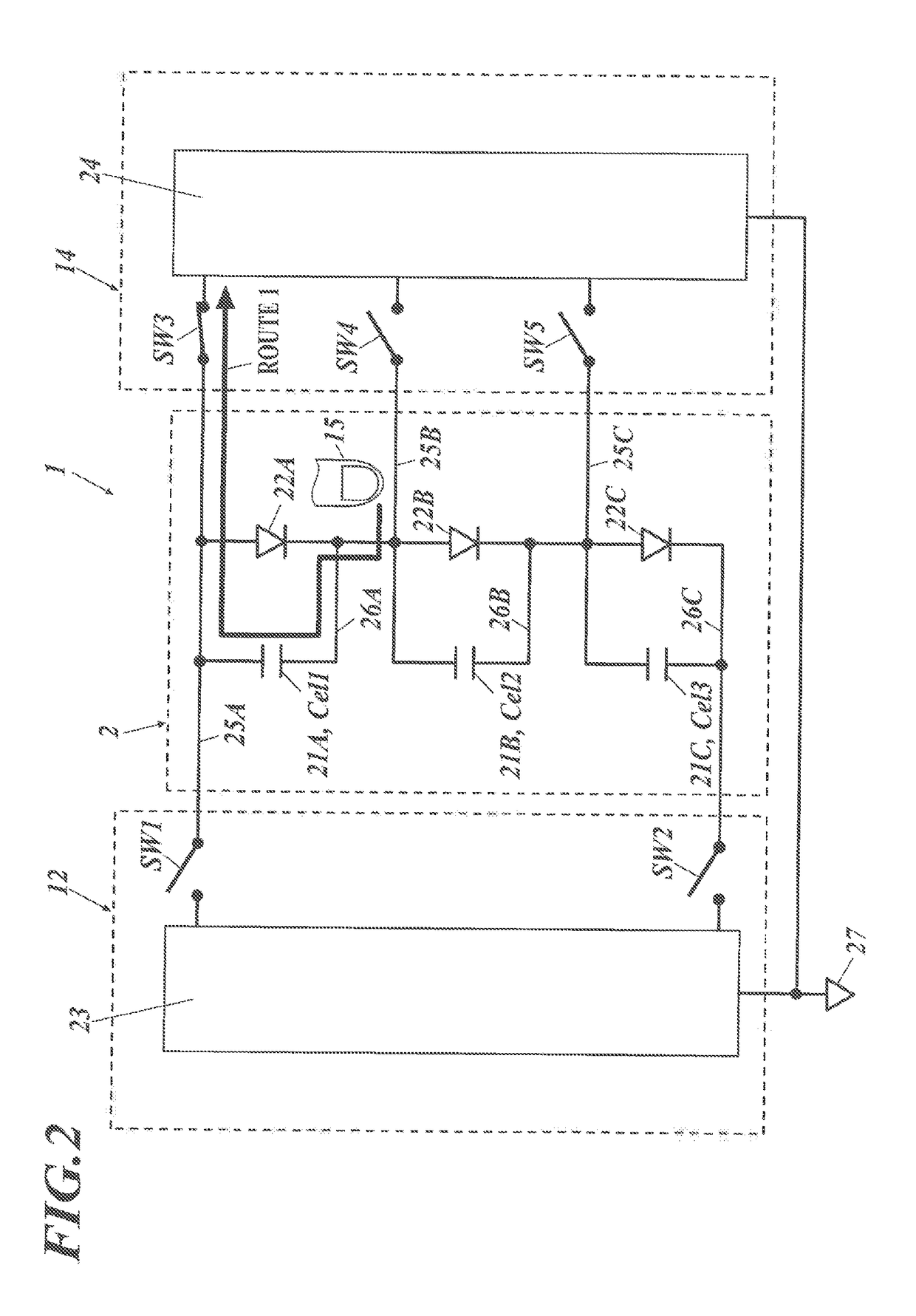
[0114]FIG. 4 illustrates an example of a driving circuit in the configuration (Embodiment 1) having switches between three organic El elements in an organic EL module of the present invention.

[0115]In FIG. 4 illustrating a circuit diagram for driving the organic EL module (1), in the same manner as in FIG. 2, the organic EL panel (2), which is illustrated on the middle of the drawing, includes an anode lead (25A to 25C) and a cathode lead (26A to 26C). Three organic EL elements (22A to 22C) (being a diode) and a parasitic capacitance (21A (Cel 1) to 21C (Cel 3)) of the organic EL elements are connected to the both leads.

[0116]In the light-emitting device driving circuit unit (12), which is illustrated on the left of the drawing, the anode lead (25A) extending from the anode (4A) (not shown) of a first organic EL element (22A) is connected to a light-emitting device driving circuit section (23) via a first switch (SW1). The cathode lead (26C) extending from the cathode (6C) (not show...

embodiment 2

[0153]FIG. 12 is a driving circuit diagram in Embodiment 2 of an organic EL module of the present invention. The organic EL module contains three organic EL elements having a switch therebetween, and the organic EL elements each respectively have a touch sensing circuit section.

[0154]The basic circuit configuration is the same configuration as described for FIG. 4 to FIG. 11. However, in the touch sensing circuit section (24) composing the touch sensing circuit unit (14), there are placed a first organic EL element (22A), an anode lead (25A), and independently a first touch sensing circuit section (24A) in SW3 line. In the same way, there are placed a second organic EL element (22B), an anode lead (25B), and independently a second touch sensing circuit section (24B) in SW4 line. And further, there are placed a third organic EL element (22C), an anode lead (25C), and independently a third touch sensing circuit section (24C) in SW5 line.

[0155]As illustrated in FIG. 12, each touch sens...

embodiment 3

[0158]In the organic EL module of the present invention, it is preferable that at least one of the paired electrodes is in a floating potential during the touch sensing term to prevent detection of the capacitance of the respective organic electroluminescent element. Further it is preferable that at least one of the paired electrodes is in a floating potential and the paired electrodes are short-circuited during the touch sensing term to prevent detection of the capacitance of the respective organic electroluminescent panel. Still further, it is preferable that both of the paired electrodes are in a floating potential.

[0159]In the organic EL module of the present invention, the light-emitting device driving circuit unit and the touch sensing circuit unit are independently installed. At the moment of touch sensing, in order to prevent detection of the electrostatic capacitance Cel between the anode and the cathode, the switch is turned off between the anode, the cathode, and the ligh...


PUM


Abstract

An object of the present invention is to provide an organic electroluminescent module having a touch sensing function, the organic electroluminescent module containing: a touch sensing circuit unit containing a capacitive touch sensing circuit section; and a light-emitting device driving circuit unit containing a light-emitting device driving circuit section for driving an organic electroluminescent panel, wherein the organic electroluminescent panel has a configuration composed of two or more organic electroluminescent elements each laid out in series, the organic electroluminescent element comprises paired opposite plate electrodes therein, one of the paired electrodes is a touch sensing electrode, the touch sensing electrode being connected to the touch sensing circuit unit, and the two or more organic electroluminescent elements laid out in series respectively have an independent sensing device to carry out touch sensing independently.

Description

TECHNICAL FIELD[0001]The present invention relates an organic electroluminescent module having a touch-sensing function, a smart device and an illumination apparatus provided with the module.BACKGROUND[0002]Examples of a conventional flat light source include a light emitting diode (hereafter, it is called as an LED) provided with a light guiding plate, and an organic light emitting diode (hereafter, it is called as an OLED).[0003]Smart devices, such as smart phones and tablets, have acquired exponential increased sales on a world scale from around 2008. These smart devices are provided with a keyboard having a flat face in view of easy handling. For example, the keyboard corresponds to the icon region including common functional key buttons provided at the bottom of a smart device. One example combination of the common functional key buttons consists, for example, of “Home” (indicated by a square mark), “Return” (indicated by an arrow mark), and “Search” (indicated by a loupe mark)...

Claims


Application Information

Patent Timeline
Patent Type & Authority Applications(United States)
IPC IPC(8): G06F3/041G09G3/3208G06F3/044
CPCG09G3/3208G06F3/0418G06F3/044G06F3/0412G09G3/14H10K50/00
Inventor OMATA, KAZUYOSHIYAGI, TSUKASA
Owner KONICA MINOLTA INC
Why Eureka
Try Eureka