
Screw spindle pump

a spindle pump and screw technology, applied in the direction of rotary piston engines, working fluids for engines, rotary or oscillating piston engines, etc., can solve the problems of unsuitability, structural length, centrifugal pumps, etc., and achieve the effect of high overall efficiency, high efficiency, and significantly more efficient working

Active Publication Date: 2022-06-28
LEISTRITZ PUMPEN
View PDF19 Cites 2 Cited by
  • Summary
  • Abstract
  • Description
  • Claims
  • Application Information

AI Technical Summary

Benefits of technology

The invention proposes a screw spindle pump that is designed for delivering cooling liquid to cool battery and power electronics in motor vehicles. It has a high efficiency of approximately 70%, which is better for the overall energy balance of the vehicle. The screw spindle pump is small in size and can operate at very high speeds. It is suitable for use in modern motor vehicles where centrifugal pumps are not suitable due to their size. The spindle is designed to be as compact as possible radially, which means that extremely slender spindles are used, which has an advantageous effect on the outer diameter of the housing.

Problems solved by technology

The fact that the screw spindle pump may be dimensioned to be of a very small format with a simultaneously high efficiency and significantly higher throughput than centrifugal pumps, and that such screw spindle pumps can also be operated at very high rotational speeds of several 1000 rpm, makes it particularly suitable for use in modern motor vehicles, where centrifugal pumps, not least because of their structural size or structural length, have proven to be unsuitable.

Method used


Image

  • Screw spindle pump
  • Screw spindle pump

Examples


Embodiment Construction

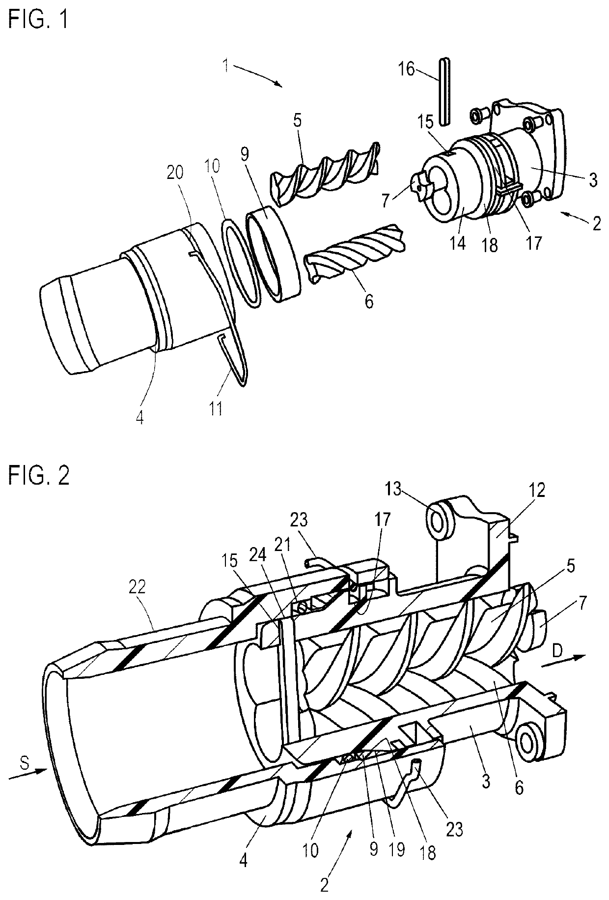
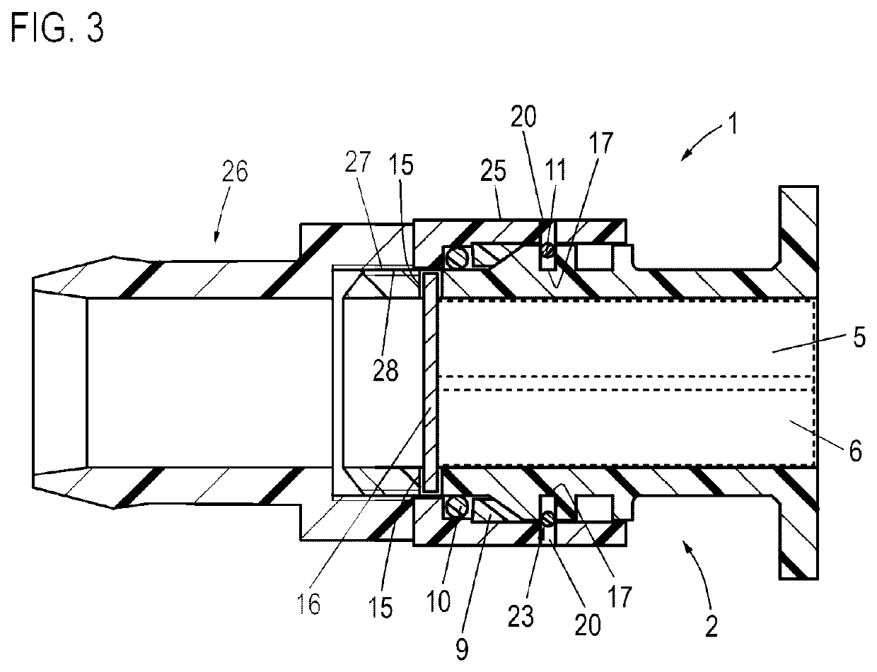
[0034]FIG. 1 shows, in the form of a basic illustration, a screw spindle pump 1 according to the invention, which is designed for delivering a cooling liquid for cooling a battery and / or power electronics or a cleaning or supply liquid of a motor vehicle. Said pump consists of a housing 2 having a first housing part 3 and having a second housing part 4, which are able to be fastened detachably to one another.

[0035]Also provided is a working spindle 5 and a running spindle 6, which, in the assembled position (see FIG. 2), interengage and mesh with one another. A coupling element 7 is able to be attached to the working spindle 5 at a corresponding connection geometry, via which coupling element a connection to a drive assembly (not shown in any more detail) in the form of an electric motor can be realized. Also provided is a support ring 9, which serves for radially supporting the second housing part 4, and a sealing element 10 in the form of a sealing ring, which serves for sealing o...


PUM


Abstract

A screw spindle pump for delivering a cooling liquid for cooling a battery and / or power electronics or a cleaning or supply liquid of a motor vehicle, including a housing in which a working spindle, which is coupled to a drive assembly, and at least one running spindle, which meshes with the latter, are accommodated, and including a feather key-like support element, which is fixed by the housing and against which the working spindle and the running spindle are axially supported. In the housing, there is provided at least one aperture through which it is possible to insert the support element, which, in the assembled position, is received with one end in the aperture and with the other end in a receiving part situated diametrically opposite the aperture, wherein the support element is secured via at least one securing element which closes the aperture at the outside.

Description

CROSS-REFERENCE TO RELATED APPLICATIONS[0001]The present application claims priority of DE 10 2019 132 653.2, filed Dec. 2, 2019, the priority of this application is hereby claimed, and this application is incorporated herein by reference.BACKGROUND OF THE INVENTION[0002]The invention relates to a screw spindle pump.[0003]In modern motor vehicles with partially or fully electric drive, use is made of correspondingly large-dimensioned batteries as well as associated power electronics, which require effective cooling since said components produce a large amount of heat during operation. For this purpose, centrifugal pumps are used, in order to deliver the cooling liquid for cooling the battery or the power electronics. A disadvantage, on the one hand, is that such centrifugal pumps have only a relatively low overall efficiency of approximately 40%, which is too low for relatively long-term use in such partially or fully electrically driving motor vehicles, since such centrifugal pumps...

Claims


Application Information

Patent Timeline
Patent Type & Authority Patents(United States)
IPC IPC(8): F01C1/08F03C2/00F03C4/00F04C18/00F04C2/08F04C11/00F04C2/16
CPCF04C2/082F04C2/165F04C11/008F04C2210/1044F04C2230/60F04C2240/30F04C2/16F04C15/00F04C2240/805F01C21/108F04C2/107F04C15/0003F04C2240/20F05B2210/11
Inventor METZ, JÜRGENPOPP, FLORIANLISSEK, KRISTIN
Owner LEISTRITZ PUMPEN
Learn More