Manufacturing method of semiconductor device

a manufacturing method and semiconductor technology, applied in the direction of semiconductor devices, electrical equipment, transistors, etc., can solve the problems of poor electrical characteristics of transistors, and achieve the effect of improving the electrical characteristics improving the reliability of a semiconductor device using an oxide semiconductor

Inactive Publication Date: 2017-05-04
SEMICON ENERGY LAB CO LTD
View PDF0 Cites 3 Cited by
  • Summary
  • Abstract
  • Description
  • Claims
  • Application Information

AI Technical Summary

Benefits of technology

The present invention improves the electrical characteristics and reliability of semiconductor devices that use oxide semiconductor. It also reduces the number of oxygen vacancies in the oxide semiconductor and prevents the transistor from becoming normally-on. This is achieved by adding oxygen to the first or third oxide semiconductor film and performing heat treatment to diffuse the oxygen vacancies into the second oxide semiconductor film. Overall, this invention provides a novel semiconductor device with improved performance and reliability.

Problems solved by technology

In a transistor using an oxide semiconductor, oxygen vacancies, which may cause localized states in an oxide semiconductor film, lead to poor electrical characteristics of the transistor.

Method used


Image

  • Manufacturing method of semiconductor device
  • Manufacturing method of semiconductor device
  • Manufacturing method of semiconductor device

Examples


embodiment 1

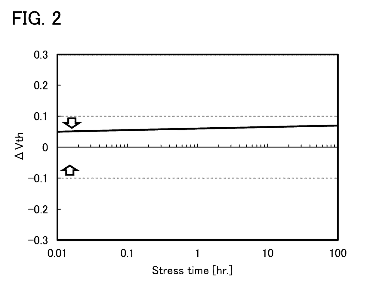
[0089]The threshold voltage of a transistor using an oxide semiconductor film including oxygen vacancies easily shifts in the negative direction, and such a transistor tends to be normally-on. This is because electric charges are generated owing to oxygen vacancies in the oxide semiconductor film, and the resistance is reduced. In addition, a transistor using an oxide semiconductor film including oxygen vacancies has such a problem that the electrical characteristics, typically, the threshold voltage, are changed with time or changed by a stress test (typically, a gate bias-temperature (BT) stress test under light irradiation). In this embodiment, a highly reliable semiconductor device with a small change in threshold voltage and a manufacturing method thereof will be described. Further, a semiconductor device with excellent electrical characteristics and a manufacturing method thereof will be described.

Structure Example of Semiconductor Device

[0090]In this embodiment, a method for ...

modification example 2

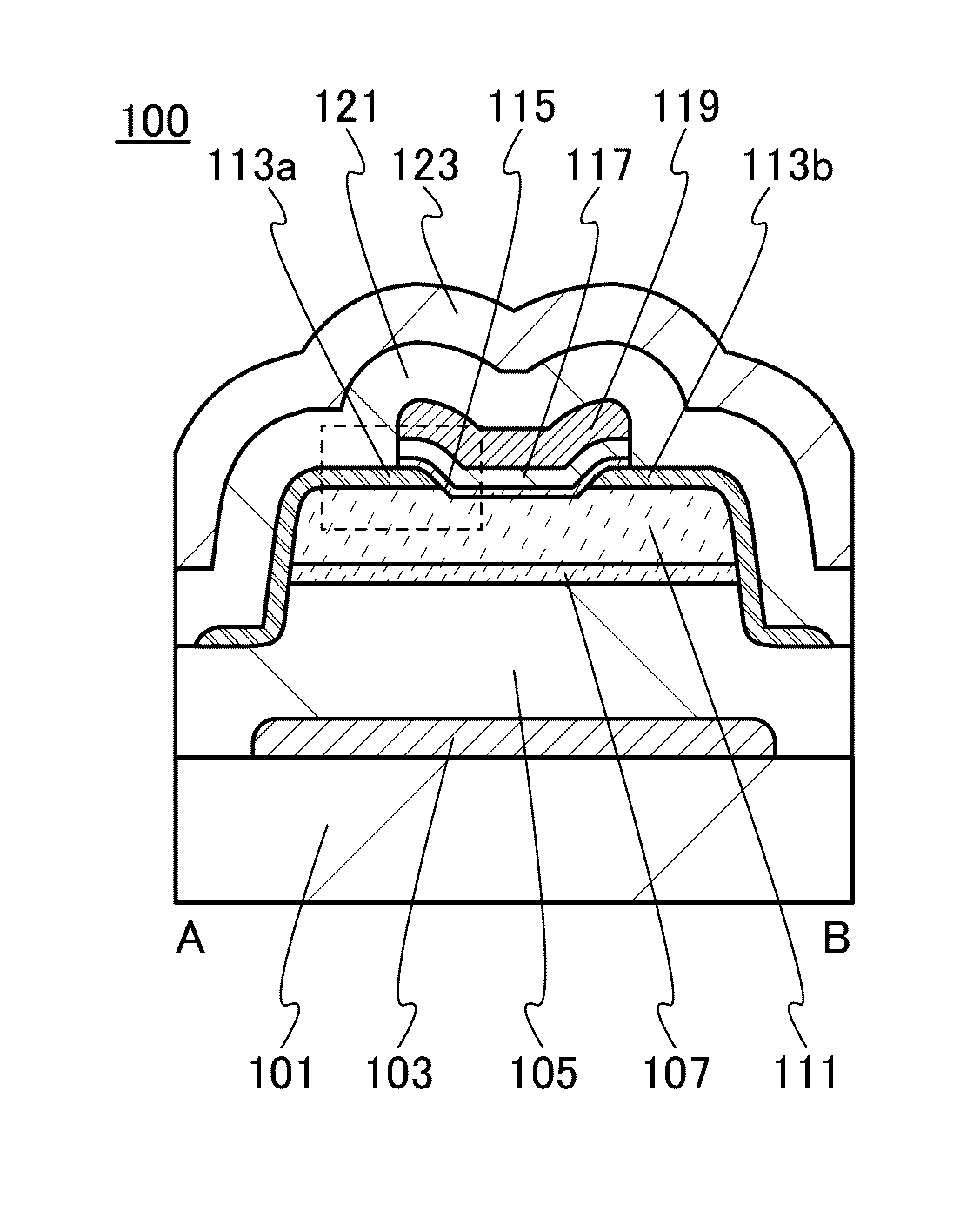
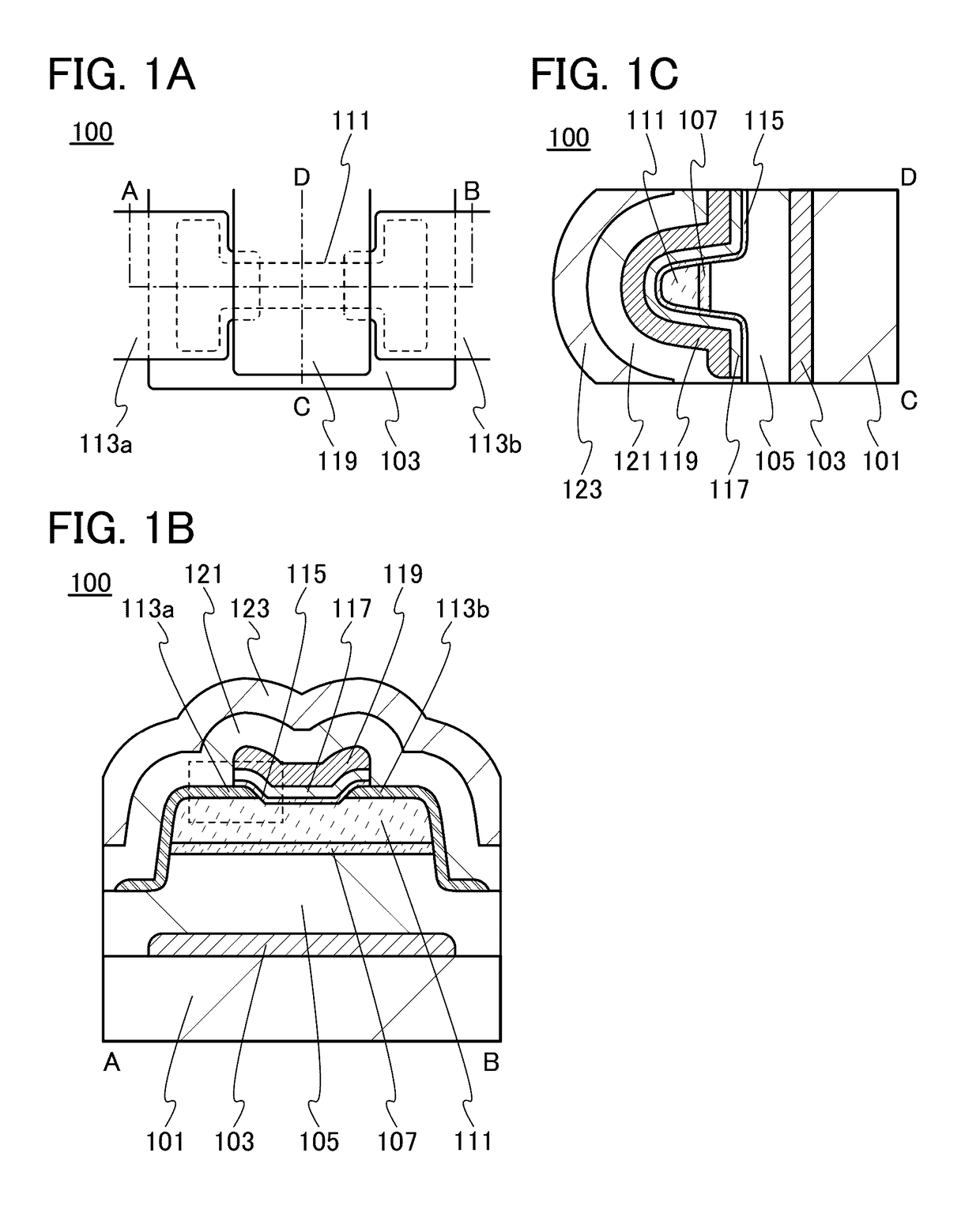
[0291]A transistor including a pair of electrodes with a different shape from that of the pair of electrodes 113a and 113b in the transistor 100 illustrated in FIGS. 1A to 1C will be described with reference to FIGS. 7A to 7D.

[0292]FIGS. 7A to 7D are a top view and cross-sectional views of a transistor 100d of a semiconductor device. FIG. 7A is a top view of the transistor 100d, FIG. 7B is a cross-sectional view taken along dashed-dotted line A-B in FIG. 7A, FIG. 7C is a cross-sectional view taken along dashed-dotted line C-D in FIG. 7A, and FIG. 7D is a cross-sectional view taken along dashed-dotted line E-F in FIG. 7A.

[0293]FIG. 7B is a cross-sectional view in the channel length direction of the transistor 100d, FIG. 7C is a cross-sectional view in the channel width direction of the transistor 100d, and FIG. 7D is a cross-sectional view in the channel width direction of the transistor 100d showing the region where the pair of electrodes and the oxide semiconductor films are stacke...

modification example 3

[0305]A transistor including the oxide semiconductor film 111 with a different shape from that in the transistor 100 illustrated in FIGS. 1A to 1C will be described with reference to FIGS. 10A to 10C.

[0306]FIGS. 10A to 10C are a top view and cross-sectional views of a transistor 100e included in a semiconductor device. FIG. 10A is a top view of the transistor 100e, FIG. 10B is a cross-sectional view taken along dashed-dotted line A-B in FIG. 10A, and FIG. 10C is a cross-sectional view taken along dashed-dotted line C-D in FIG. 10A.

[0307]FIG. 10B is a cross-sectional view in the channel length direction of the transistor 100e and FIG. 10C is a cross-sectional view in the channel width direction of the transistor 100e.

[0308]Note that in FIG. 10A, the substrate 101, the gate insulating film 105, the oxide semiconductor film 107, the gate insulating film 117, the insulating film 121, the insulating film 123, and the like are not illustrated for simplicity.

[0309]As illustrated in FIG. 1...


PUM


Abstract

A method for manufacturing a semiconductor device includes the steps of forming a first insulating film over a first gate electrode over a substrate while heated at a temperature higher than or equal to 450° C. and lower than the strain point of the substrate, forming a first oxide semiconductor film over the first insulating film, adding oxygen to the first oxide semiconductor film and then forming a second oxide semiconductor film over the first oxide semiconductor film, and performing heat treatment so that part of oxygen contained in the first oxide semiconductor film is transferred to the second oxide semiconductor film.

Description

CROSS-REFERENCE TO RELATED APPLICATIONS[0001]This application is a continuation of U.S. application Ser. No. 14 / 719,431, filed Dec. May 22, 2015, now allowed, which claims the benefit of a foreign priority application filed in Japan as Serial No. 2014-107570 on May 23, 2014, both of which are incorporated by reference.TECHNICAL FIELD[0002]The present invention relates to an object, a process (including a method and a manufacturing method), a machine, a manufacture, or a composition of matter. In particular, one embodiment of the present invention relates to a semiconductor device, a display device, a light-emitting device, a driving method thereof, a manufacturing method thereof, or the like. In particular, one embodiment of the present invention relates to a semiconductor device, a display device, a memory device, a light-emitting device, or the like including an oxide semiconductor.[0003]In this specification, the category of semiconductor devices includes all devices that can fun...

Claims


Application Information

Patent Timeline
Patent Type & Authority Applications(United States)
IPC IPC(8): H01L29/66H01L21/465H01L21/02H01L21/441H01L29/786H01L21/477
CPCH01L29/66969H01L29/7869H01L21/477H01L29/78648H01L21/02565H01L21/441H01L21/465H01L21/02255H01L21/8258H01L27/0688H01L27/088H01L27/1225H01L29/78696H01L29/401H10B41/70H01L29/786
Inventor YAMAZAKI, SHUNPEITANAKA, TETSUHIROSAKAKURA, MASAYUKITOKUMARU, RYOYAMANE, YASUMASASATO, YUHEI
Owner SEMICON ENERGY LAB CO LTD
Why Eureka
Try Eureka