Wavefront Multiplexing in Passive Optical Network with Remote Digital Beam Forming

a technology of digital beam forming and optical network, applied in the field of wavefront multiplexing in passive optical network with remote digital beam forming, can solve the problems of increasing complexity, cost-effective deployment of pons for small cell backhauling using existing infrastructure, and affecting data transport privacy and survivability, so as to improve privacy and survivability. the effect of data transpor

Active Publication Date: 2017-05-04
SPATIAL DIGITAL SYST
View PDF0 Cites 6 Cited by
  • Summary
  • Abstract
  • Description
  • Claims
  • Application Information

AI Technical Summary

Benefits of technology

[0059]The present invention relates to orthogonal modes propagations in a multi-dimensional communications channel via multidimensional waveforms The architecture will enable operator to allocate existing asset (e.g. bandwidth) to various subscribers dynamically. It also relates to Passive Optical Networks (PON), Small cell, Wavefront Multiplexing or K-muxing, and digital beam forming (DBF) and remote digital beam forming (RDBF). The K-muxing may be implemented to function in incoherent modes to enhance privacy and survivability in data transport. The same K-muxing may also be implemented for operations in coherent modes for power combining and resource allocations.

Problems solved by technology

As demand continues to increase, it becomes increasingly difficult to satisfy this requirement, particularly in densely populated areas and remote rural areas.
However, cost-efficient deployments of PONs for small cell backhauling using existing infrastructure adds complexity because the existing resources must be taken into account.
Most of the concerns and difficulties in implementation of RBF or RDBF are related to dynamic calibrations, and equalization of multiple channels in a feederlink, maintaining coherent operation among multiple array elements on board satellites.
Thus dynamic calibration and equalizations among propagation channels in feederlink may become an issue.
While the equipment in each home is capable of transmitting at over 1,250 Mbps, it can only do so during its allotted time on the fiber, and therefore it is not uncommon for each subscriber in a legacy PON system to only achieve sustained data rates of around 30 Mbps.
However, this sharing of fiber is one of the main factors limiting higher data rates to subscribers.

Method used


Image

  • Wavefront Multiplexing in Passive Optical Network with Remote Digital Beam Forming
  • Wavefront Multiplexing in Passive Optical Network with Remote Digital Beam Forming
  • Wavefront Multiplexing in Passive Optical Network with Remote Digital Beam Forming

Examples


embodiment 1

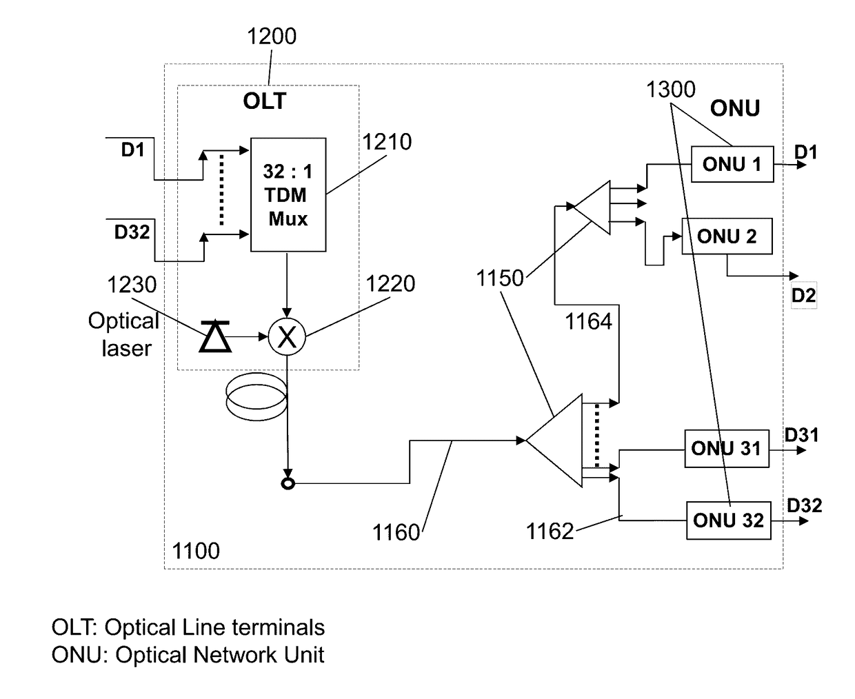
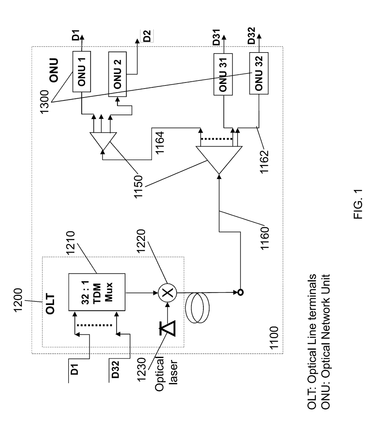
[0104]FIG. 2 depicts a PON 1100 connected to a user processor 2100 for a second user through one of the ONUs 1300, the ONU 2 designated as for a second user with a designated data bit stream D2. The user processor 2100 comprises a router 2110 which is connected to a picocell hub 2120 for cell phone wireless connectivity via a picocell hub antenna 2232. Cellphone 2236 can be operational within the antenna coverage or field-of-view (FOV) 2234. Picocell is also referred as small-cell. The router 2110 may also be connected to WiFi hub 2130 for wireless connectivity via a WiFi hub antenna 2132 for many personal devices 2136. A notebook as one of personal devices 2136 may connect to Internet when it is within the FOV 2134 of the WiFi hub antenna 2132.

[0105]Referring to FIG. 2, each of the optical network units 1300 (ONUs) is arranged between one of the optical dividers 1150 and a corresponding one of thirty-two user processors 2100. In the downstream direction, each of the optical network...

embodiment 2

[0107]FIG. 3 is a down link or a forward direction schematic diagram showing a passive optical network (PON) 1100 in combination with wave-front multiplexing (K-muxing 130) and WF demultiplexing (K-demuxing 140) techniques for dynamically allocating the resource of the passive optical network system for multiple user processors 2100 according to an embodiment of the present invention. We shall refer to the K-muxing 130 in a preprocessor and K-demuxing 140 in post-processors. They are new functions in conjunction with a PON 1100 in this patent application. In short the K-muxing 130 before OLT 1200 in a pre-processor 1800 and the K-demuxing 140 after ONUs 1300 in post-processors 1340 in forward direction may be referred as new or additional functions for the OLT 1200 and the ONUs 1300. These new functions may be implemented by additional S / W and / or electronics boxes in the OLT and the ONUs. We referred this architecture, a PON in a combination of K-muxing 130 and K-demuxing 140, as “K...

embodiment 3

[0132]FIG. 4 depicts the same functional blocks as those in FIG. 2, except in the user side. The updated user processor 3100 comprises two smart array antennas; a first one for picocell hub 2110 and a second one for a WiFi hub 2130. The picocells are also referred to as small cells. 4 antenna array elements 2232 for the picocell hub 2120 are connected to a device for function of digital beam forming (DBF) 3120. A first smart array is formed by the 4 elements 2232 and a first one (DBF 1) of the DBF 3120 for the Picocell hub 2120.

[0133]The first smart array shall operate on a cell phone band, connecting multiple cell phones 2236 to the picocell hub 2120 concurrently over a common fields of view 2234. The smart array may form concurrent tracking beams with orthogonal beam patterns. For three cell phones 2236, the smart array shall automatically form three concurrent beams. The first beam shall be dynamically optimized following current position of a first cellphone with a beam peak at ...


PUM


Abstract

Four independent technologies are incorporated in this invention to efficiently and cost effectively implement dynamic last mile connectivity. The four technologies are passive optical networks (PON), Small cell, wavefront multiplexing (or K-muxing), and digital beam forming (DBF). We have filed US patents for communications architectures featuring K-muxing overlaid over low cost of PON. Those inventions relate particularly to resource allocation in passive optical networks (PON) via wavefront multiplexing (WF-muxing or K-muxing) and wavefront demultiplexing (WF-demuxing or K-demuxing). The “WF-muxing in PON” can be configured for performing remote digital beam forming (RDBF) over a service area covered by multiple small cells. The RDBF may generate multiple shaped beams with enhanced connectivity and better isolations over a same frequency slot concurrently to serve multiple users over the coverage area.

Description

CROSS-REFERENCE TO RELATED APPLICATIONS[0001]This application, titled “Wavefront Multiplexing in Passive Optical Network with Remote Digital Beam Forming” (or K-Muxing in PON with RDBF), is related to[0002]1. U.S. Pat. Appl. Pub. No. 20130223840; “Resource Allocation in PON Networks via Wave-front Multiplexing and De-multiplexing,” published on Aug. 29, 2013,[0003]2. U.S. Pat. No. 8,111,646; “Communication System For Dynamically Combining Power From A Plurality Of Propagation Channels In Order To Improve Power Levels Of Transmitted Signals Without Affecting Receiver And Propagation Segment,” Issued on Feb. 7, 2012.[0004]3. U.S. Pat. No. 8,098,612; “Apparatus And The Method For Remote Beam Forming For Satellite Broadcasting Systems,” Issued on Jan. 17, 2012.[0005]4. U.S. Pat. Appl. Pub. No. 20110197740; “Novel Karaoke and Multi-Channel Data Recording / Transmission Techniques via Wavefront Multiplexing and Demultiplexing,” published on Aug. 18, 2011.[0006]5. U.S. Pat. Appl. Pub. No. 20...

Claims


Application Information

Patent Timeline
Patent Type & Authority Applications(United States)
IPC IPC(8): H04B7/06H04B7/04H04B10/2575
CPCH04B7/0617H04B7/0413H04B10/2575H04B10/25753
Inventor CHANG, DONALD C.D.LEE, JUO-YUCHEN, STEVE K.
Owner SPATIAL DIGITAL SYST
Why Eureka
Try Eureka