Workstation of a two-for-one twisting or cabling machine

Active Publication Date: 2017-05-11
SAURER TECH GMBH & CO KG
View PDF14 Cites 7 Cited by
  • Summary
  • Abstract
  • Description
  • Claims
  • Application Information

AI Technical Summary

Benefits of technology

[0048]Both with a yarn-supply unit and also with a yarn brake, the yarn tension of a circulating yarn balloon can be adjusted very precisely, that is, such a controllable yarn-tension influencing device, in conjunction with an advantageous operating position of the balloon-yarn-guide-eye, allows an optimisation of the size and the shape of the circulating yarn balloon at all times, and accordingly, a significant reduction in the energy requirement of the relevant workstation.
[0049]In an advantageous embodiment, the c

Problems solved by technology

However, since large yarn balloons are known to lead to relatively large ventilation losses and therefore to an increased energy requirement of the workstations of the two-for-one twisting or cabling machines, various attempts have already been made in the past, especially in conjunction with less friction-sensitive yarn materials, such as cotton, to reduce or respectively to limit the diameter of the yarn balloons.
However, the disadvantage with these known two-for-one yarn-twisting spindles is the relatively long physical contact of the circulating yarn balloon with the stationary balloon limiter.
In the case of

Method used


Image

  • Workstation of a two-for-one twisting or cabling machine
  • Workstation of a two-for-one twisting or cabling machine
  • Workstation of a two-for-one twisting or cabling machine

Examples


Embodiment Construction

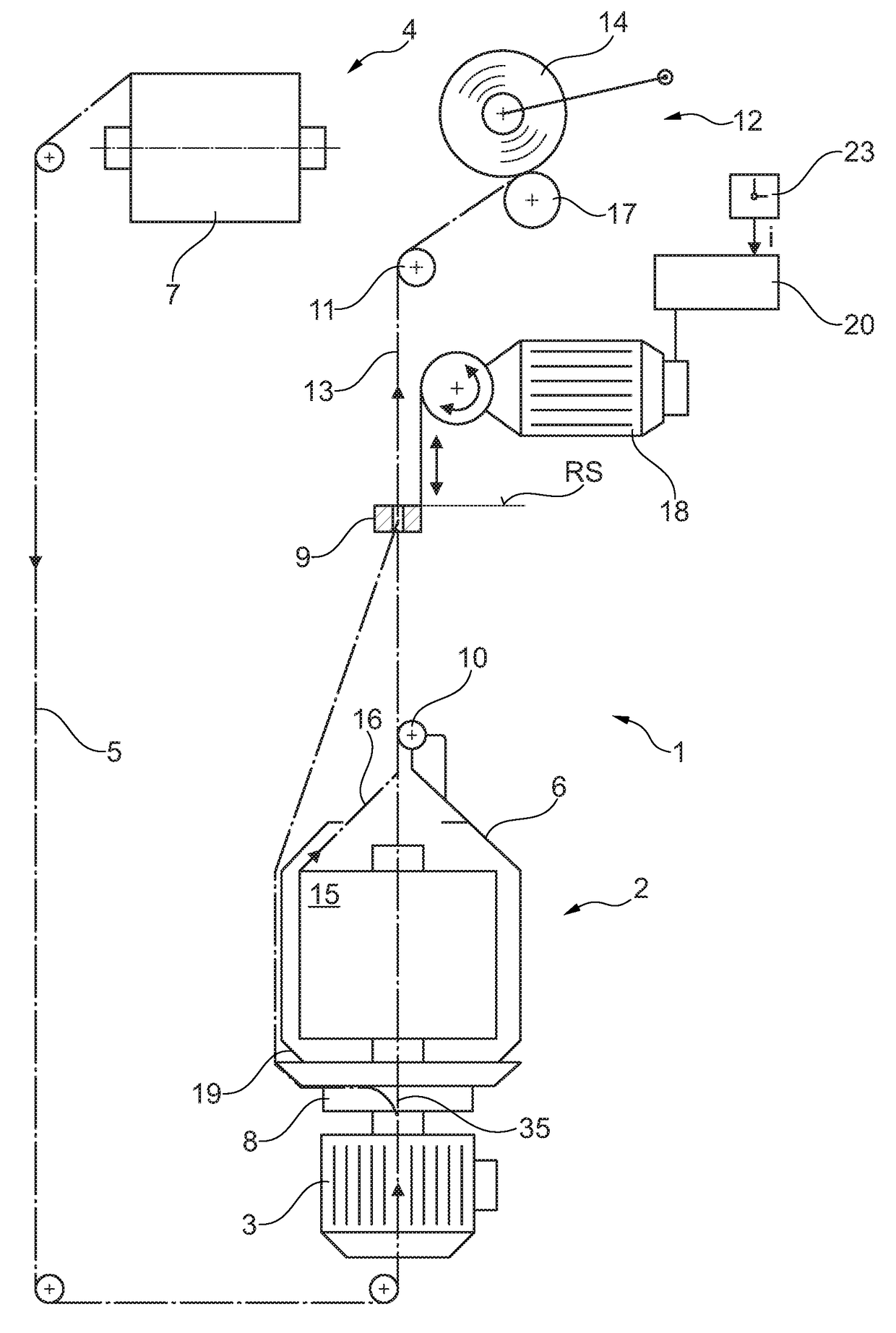
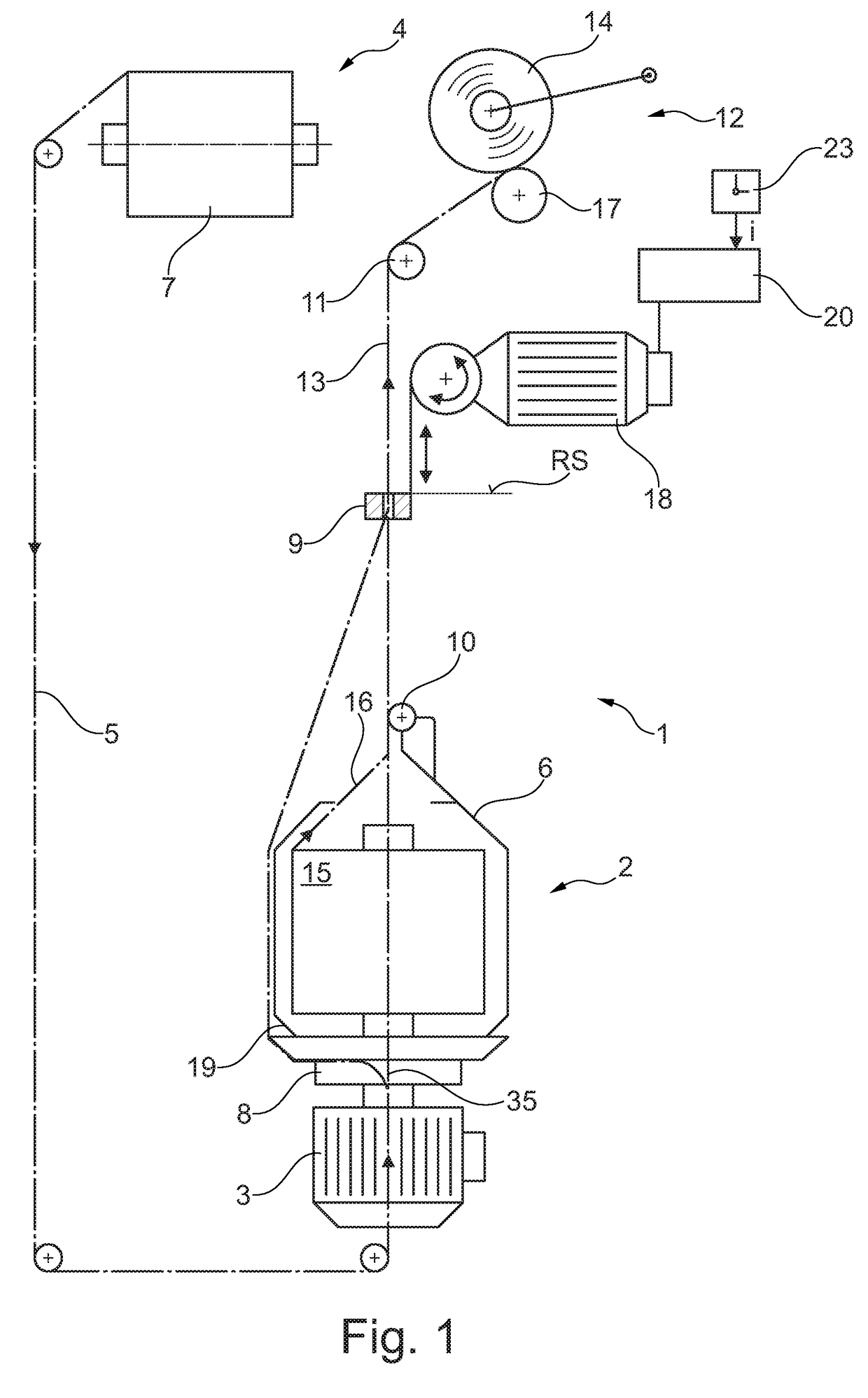
[0061]FIG. 1 shows schematically, in lateral view a workstation 1 of a cabling machine with a balloon-yarn-guide-eye 9 which can be height adjusted by a drive 18. The drive 18 is connected to a control device 20. The workstation 1 is disposed at a standstill, that is, the spindle drive 3 is switched off; the spindle 2 does not rotate.

[0062]As suggested in FIG. 1, a bobbin rack 4 (not illustrated in greater detail), which generally serves to accommodate a plurality of feed bobbins 7, is positioned above or behind the workstation 1.

[0063]A so-called outer yarn 5 is withdrawn from at least one of these feed bobbins 7 referred to in the following as a first feed bobbin 7.

[0064]As is evident, the outer yarn 5 withdrawn from the first feed bobbin 7 is deflected several times before it enters the hollow rotary axle of the spindle drive 3 in the region of a rotational axis 35 of the spindle 2.

[0065]The outer yarn 5 leaves the hollow rotary axle of the spindle drive 3 through a so-called yar...


PUM


Abstract

A workstation (1) of a two-for-one twisting or cabling machine which comprises a rotatably mounted spindle (2) and a balloon-yarn-guide-eye (9) height-adjustable by means of a drive (18, 29) coupled to a control device (20) which controls the drive (18, 29) in such a manner that it displaces the balloon-yarn-guide-eye (9) between operating positions (AP1, AP2) dependent upon production parameters and a resting position (RS) advantageous in the case of production interruptions and transient operating phases associated with the latter. A device (21, 23, 24, 25) is present for detecting a measured value (i), which is made available to the control device (20) and which causes the control of the drive (18, 29) to change the position of the balloon-yarn-guide-eye (9).

Description

CROSS-REFERENCE TO RELATED APPLICATIONS[0001]This application claims priority from German National Patent Application No. DE 10 2015 014 382.4, filed Nov. 9, 2015, entitled “Arbeitsstelle einer Doppeldrahtzwirn-oder Kabliermaschine”, the entire contents of which are incorporated herein by reference.FIELD OF THE INVENTION[0002]The present invention relates to a workstation of a two-for-one twisting or cabling machine which comprises a rotatably mounted spindle and a balloon-yarn-guide-eye height-adjustable by means of a drive.BACKGROUND OF THE INVENTION[0003]Since a single yarn often cannot satisfy the requirements which are placed on it with regard to its strength and / or its uniformity during further processing or in the finished product, it is conventional in the textile industry to initiate a yarn finishing by twisting two or more yarns together. This textile process of yarn finishing is generally designated as yarn-twisting, wherein, however, a distinction is made between differe...

Claims


Application Information

Patent Timeline
IPC IPC(8): D01H7/86D01H1/10D01H1/16D01H1/244D01H9/18
CPCD01H7/86D01H1/244D01H1/103D01H1/166D01H9/18D01H1/10D01H7/868D01H13/00D01H13/26D02G3/28D01H1/106D02G3/285D07B2207/4009
Inventor RAISICH, ANDREJSCHNITZLER, JURGEN
Owner SAURER TECH GMBH & CO KG
Why Eureka
Try Eureka