
Post-tensioning apparatus and system for structures

a technology of post-tensioning apparatus and system, which is applied in the direction of construction, building repair, building reinforcement, etc., can solve the problems of low stability of cement patches, high risk of repeated failure of cement patches, and difficulty in adjusting the strength of cement patches, so as to achieve a higher localized concentration of stress and strengthen structural stability

Inactive Publication Date: 2017-05-11
WEISE GARY
View PDF20 Cites 3 Cited by
  • Summary
  • Abstract
  • Description
  • Claims
  • Application Information

AI Technical Summary

Benefits of technology

The present invention provides an apparatus for repairing concrete structures by applying a tensile load to a prepared surface. The apparatus includes a tensioning mechanism and tension application components that can be engaged with the tensioning mechanism. The tension application components can be in the form of a plate-form or parallel post structures that distribute the load applied to the structure and provide a post-tensioning effect to a larger area. The invention allows for the pre-load of the apparatus without further tensioning it, and can mitigate tensile forces on the concrete by placing the apparatus in tension. The technical effects of the invention include improved structural stability and reduced risk of damage to the structure being repaired.

Problems solved by technology

However, the lack of strength afforded by cements, often referred to as hydraulic cement, proves problematic.
When considering the structural integrity of a concrete installation, the cost of repeated failure depends upon the application of the concrete.
And cement patches have a high risk of repeated failure due to weak bond and structural integrity of the cement.
Contrasto '340 fails to provide any method of tension application to the concrete.
The higher ductility of steel as compared to concrete does not prevent the movement of the concrete beyond a failure threshold and therefore cannot prevent further cracking in the localized region and Contrastro '557 fails to provide the ability to pre-tension the structure or provide post-tensioning to the concrete structure.
These tensioning mechanisms, however, are limited in travel.
If the apertures created for the posts are spaced too far apart, the user may not be able to install the metal member.
If the apertures created for the posts are too close together, the user may not be able to tension the metal member as prescribed.

Method used


Image

  • Post-tensioning apparatus and system for structures
  • Post-tensioning apparatus and system for structures
  • Post-tensioning apparatus and system for structures

Examples


Embodiment Construction

[0051]In certain embodiments of the present invention, a modular apparatus and system provides tension to existing structures, such as an existing concrete installation, wherein it is desired to provide structural reinforcement. Tensioning may be desired in many scenarios such as the cross-linking of independently poured concrete installations or providing tension in “post-tensioning” to repair a concrete installation using tensile strengthening features. The application of metal structure for the tensile reinforcement is typically placed across a mechanical failure zone such as a fissure or crack where the concrete installation has mechanically failed.

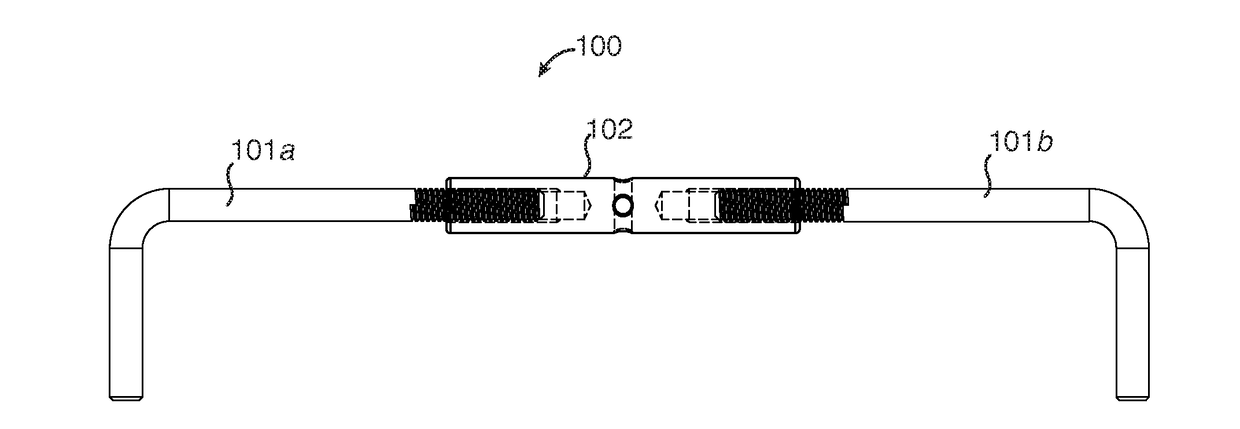
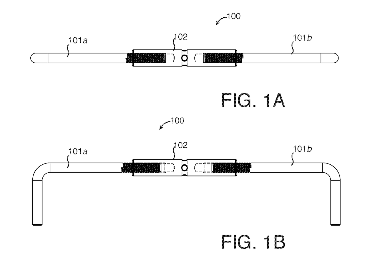
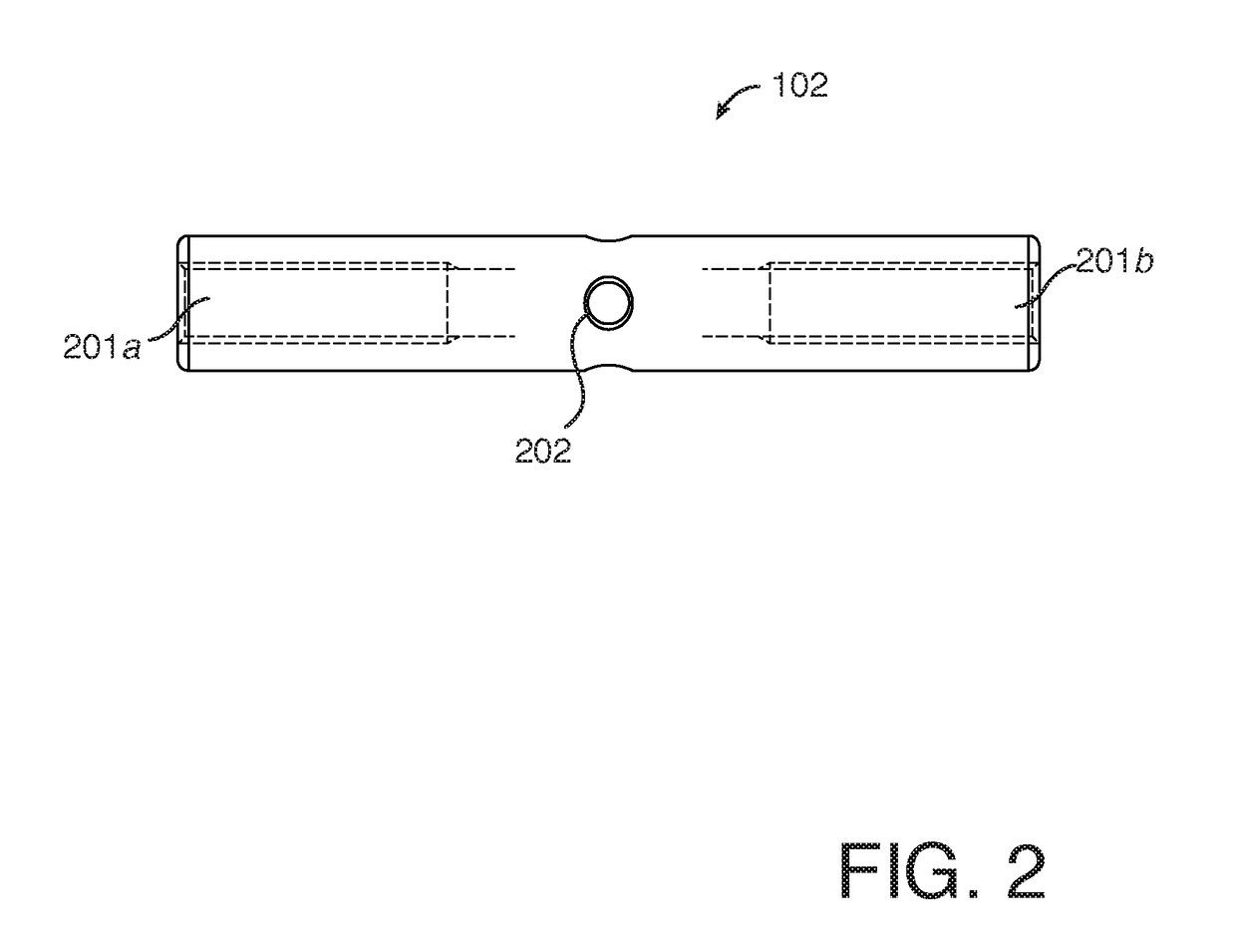
[0052]An apparatus 100, as shown in FIGS. 1A and 1B, embodying the inventive principles of the invention comprises at least two tension application components 101a and 101b and one tensioning mechanism 102 disposed and attached therebetween. When the tension application components 101 are constrained, the actuation of the tensioning m...


PUM


Abstract

The present invention pertains in general to post-tensioning apparatus and systems surrounding the fabrication and repair of concrete and other construction materials. The present invention surrounds apparatus and system directed to the post-tensioning for reinforcement of existing and new concrete structures through the application of tensile forces between two attachment points anchored to the structure to be mended.

Description

CROSS REFERENCE TO REFERENCE TO RELATED APPLICATIONS[0001]This application claims the benefit of U.S. Provisional Patent Application 62 / 253,681 entitled “Post-Tensioning Apparatus and System for Structures” filed on Nov. 11, 2015, the entire contents of which are incorporated herein by reference in its entirety for all purposes.FIELD OF THE INVENTION[0002]The present invention pertains in general to post-tensioning apparatus and systems surrounding the fabrication and repair of concrete and other construction materials. The present invention surrounds apparatus and system directed to the post-tensioning for reinforcement of existing and new concrete structures through the application of tensile forces between two attachment points anchored to the structure to be mended.BACKGROUND OF THE INVENTION[0003]The field of concrete installation and maintenance, particularly surrounding structural or load bearing concrete, requires site preparation and formula of mix to create the desired pre...

Claims


Application Information

Patent Timeline
Patent Type & Authority Applications(United States)
IPC IPC(8): E04G23/02E04C5/08
CPCE04C5/08E04G23/0218E04C5/165
Inventor WEISE, GARY
Owner WEISE GARY
Learn More