Exercise Sauna Having Far Infrared Heating Elements and Configurable Seating

a far infrared heating element and sauna technology, applied in gymnastics, programme control, instruments, etc., can solve the problems of individual sweating, unfavorable use, and inability to move to a different location, so as to facilitate a solution, increase user comfort, and facilitate flexible seating solutions

Inactive Publication Date: 2017-05-11
SHURTLEFF DAVID FLOYD
View PDF8 Cites 11 Cited by
  • Summary
  • Abstract
  • Description
  • Claims
  • Application Information

AI Technical Summary

Benefits of technology

[0026]A further advantage of the present invention is encompassed in the seating options provided. While standard bench seats limit space available within the sauna cabin, the present invention facilitates a solution to this lack of versatility and increases the user's comfort, by providing more versatile seating solutions. Instead of being limited to a fixed bench seat, the present invention includes a hinged bench seat, allowing the user to lift the seat by way of hinges, fold the bench seat into a vertical position, and attach the folded seat to the back wall inside the sauna. The hinged seat not only allows the user to move the bench seat out of the way, increasing floor space within the sauna, but also allows access to a single, pedestal-style seat that may be stored beneath the bench seat while the bench is in the down position. The single, pedestal-style seat may further be affixed to the floor of the sauna giving the user additional seating options and facilitating the conduct of an exercise routine using the sauna's integral “D” rings, discussed below. The seating options further provide freedom of movement and convenience for the user when the seat is in use, and easily stores underneath the fold down bench, out of site, when not in use.
[0027]Still another advantage of the present invention is the plurality of “D” rings” or other similar devices installed within the interior of the sauna allowing the user to exercise while using the FIR sauna. These “D” rings can be used as attachment points for exercise implements such as elastic bands or even small workout machines, while the additional space provided enables a user to move about, stretch, perform exercises, and enjoy more freedom of movement within the confines of a FIR sauna, all while simultaneously benefiting from the deep penetrating FIR heat.
[0028]To facilitate the incorporation of the “D” rings into the structural design of the sauna cabin and provide a stable and secure mounting point, the walls of the cabin also incorporate an external curvature or arch-shape increasing the structural strength of the cabin. The external curvature provides additional strength by distributing force across the wall, and away from the center of force on the “D” ring, (such like the support provided by an arch) counteracting opposing forces imparted on the interior of the cabin when an individual makes use of the “D” rings during exercise.
[0029]Another embodiment of the present invention is an access control system that allows certain users the ability to energize a sauna for personal use. The system may be energized for a preset period of time or may be energized for a period of time related to a monetary value associated with the user's account. The system consists at least of a remote computer running access control software, a wireless transceiver located at the sauna, a Network access controller, a card reader connected to the access controller, and a relay that controls power to a sauna control panel. The sauna control panel connects to the sauna's heaters, lights, and any other devices installed in the sauna, such as speakers or a television.
[0030]Also included is a flow chart illustrating the process associated with operation of the sauna and the access control system.

Problems solved by technology

The old-fashioned hot rock saunas require extreme, and often, unsafe heat, which warms the room, the walls, and the entire sauna environment prior to transferring any significant heat to the individual seated within the sauna.
In addition, once constructed in place, traditional electric heating elements in hot rock saunas have considerable power requirements and are often nearly impossible to move to a different location.
In addition, this heating causes the individual to sweat, thus achieving health benefits similar to those from a traditional rock sauna heating techniques.
Traditional hot rock saunas typically operate at temperatures ranging from 180° F. to 190° F. This high heat can be uncomfortable or even dangerous for some people, especially those with cardiovascular or respiratory problems and can limit the time one can spend in the sauna.
This, in turn, limits the amount of sweat that can be produced due to an individual's tolerance of the environment, reducing the amount of therapy obtainable.
The heavy, thick air can be difficult to breathe and evaporation can dry out membranes in the nose and eyes, furthering discomfort.
The drawback to ceramic heaters is that they tend to produce a shorter wavelength infrared energy than optimum for an FIR sauna application.
This is troublesome because the human body does not as easily absorb shorter infrared wavelengths as it does longer FIR wavelengths.
This renders sauna heaters that use only ceramic heating elements (and thus shorter wavelengths) less therapeutic.
The drawback of carbon heaters is that while they produce high quality FIR heat in the desired wavelength range, they do not commonly produce a significant amount of the energy, placing them lower on the emissivity curve than a ceramic heater alone.
A further limitation of typical saunas is interior space.
Moreover, while there is some flexibility in the user's physical position on the bench while seated, benches are fixed in place, restricting the user's seating options, further limiting floor space.
This also leaves room for little more than simply sifting in place and sweating, as opposed to maximizing time spent with exercise or stretching.

Method used


Image

  • Exercise Sauna Having Far Infrared Heating Elements and Configurable Seating
  • Exercise Sauna Having Far Infrared Heating Elements and Configurable Seating
  • Exercise Sauna Having Far Infrared Heating Elements and Configurable Seating

Examples


Embodiment Construction

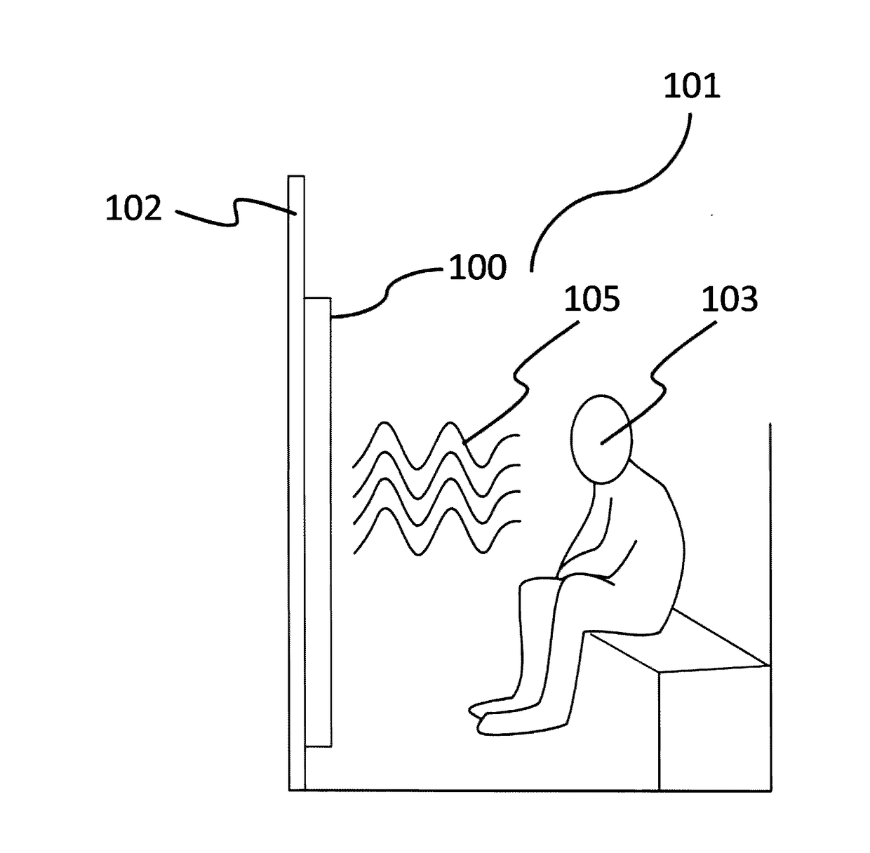
[0059]Referring initially to FIG. 1, a cut away view of an exemplary IR sauna cabin, generally labeled 101, is depicted showing an individual 103 seated therein. The far infrared (“FIR”) heating element of the present invention, generally labeled 100, is shown installed in wall 102 of sauna cabin 101. The FIR heating element 100 is shown radiating combined FIR energy 105 in order to heat the individual 103 and cause individual 103 to sweat, providing therapeutic benefits, such as resonant absorption of the FIR energy 105 within individual's 103 bodily tissues.

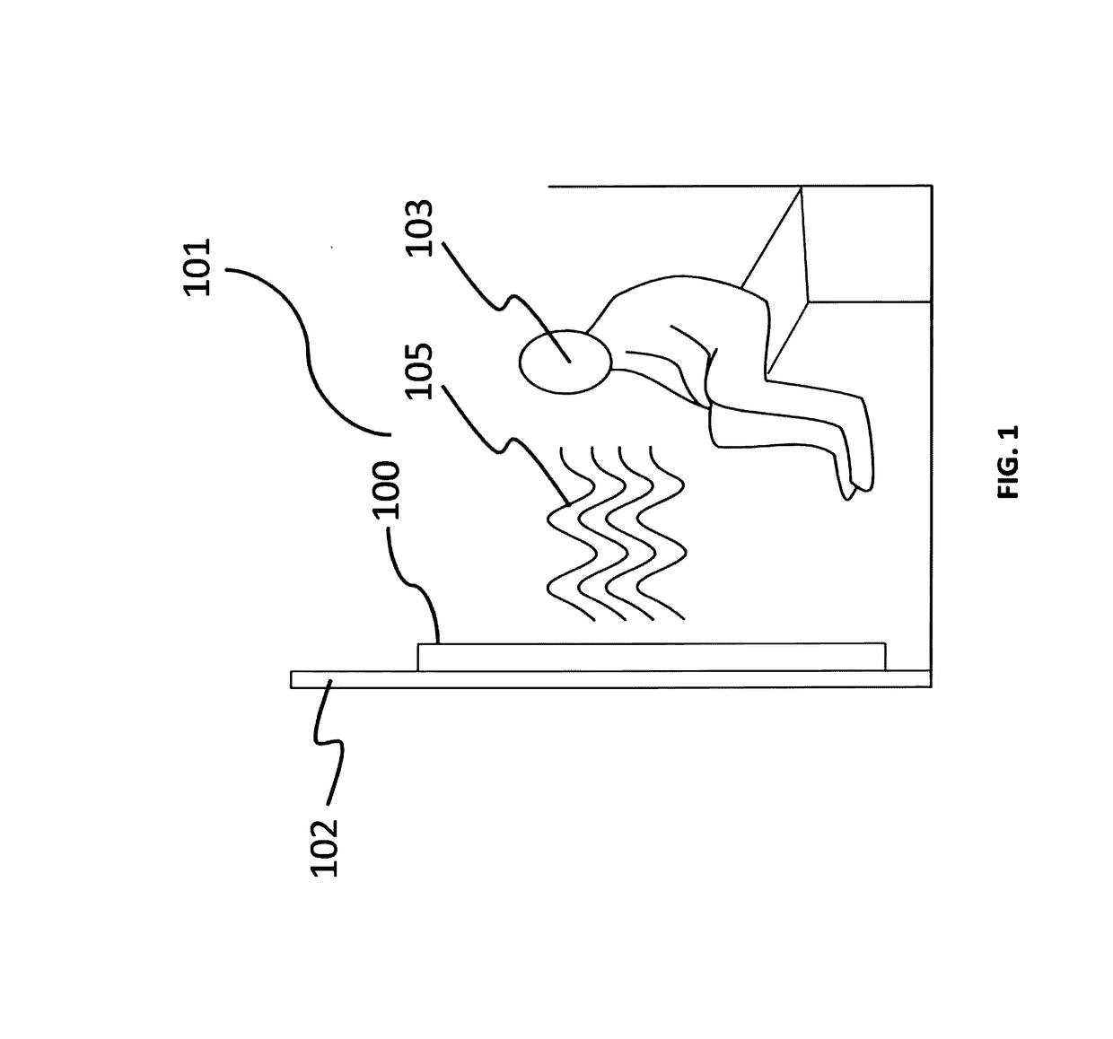
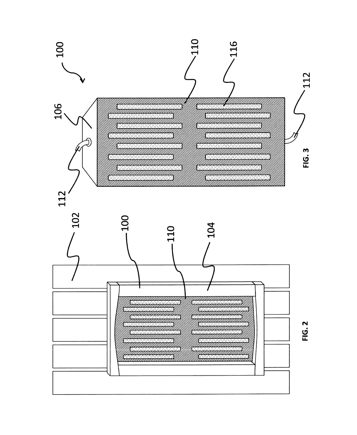
[0060]Referring now to FIG. 2, FIR heating element 100 is depicted, installed in a sauna wall 102. The FIR heating element 100 of the present invention is contemplated herein as a sauna heater, thus it is shown installed in a wooden enclosure 104, however it should be appreciated by those skilled in the art, that the FIR heating element 100 may be used for other purposes or installed in a variety of other enclosures, such as me...


PUM


Abstract

A far infrared (“FIR”) sauna cabin equipped with a far infrared (“FIR”) heating elements constructed of ceramic, carbon, and/or light emitting diodes (“LED”), designed for therapeutic use in a sauna, capable of emitting far infrared energy, and heating an individual's skin for purposes of rejuvenation, anti-aging, weight loss, and acne therapy. The FIR heating element emits IR energy in a wavelength and frequency optimum for resonant absorption by the human body, resulting in the release of toxins stored within subcutaneous fatty deposits, which are then carried out of the person's system as he or she sweats. The FIR sauna is operated by a system comprising a local control system and a remote computer running access control software. A user account is configured containing a user's allowed privileges. When a user swipes an access card, the remote computer verifies the requested privilege. If allowed, the local system energizes the sauna system.

Description

[0001]This application is a Continuation-In-Part of, and claims the benefit of priority to, U.S. Utility application Ser. No. 13 / 933,018 entitled “Exercise Sauna Having Far Infrared Heating Elements And Configurable Seating”, filed Jul. 1, 2013 and currently co-pending, which in turn claims the benefit of priority to U.S. Provisional Patent Application Ser. No. 61 / 666,839 entitled “Far Infrared Sauna Having A Portable Seating Device, A Heated Led Panel, And An Exercise System”, filed Jun. 30, 2012, and U.S. Provisional Patent Application Ser. No. 61 / 804,284 entitled “Sauna Having A Far Infrared Heating Elements, A Heated Panel, Portable Seating Device, And An Exercise System”, filed Mar. 22, 2013, with both provisional applications currently expired.BACKGROUND OF THE INVENTION[0002]Sauna heater technology has advanced far beyond the old-fashioned hot rock era. The health benefits of saunas have been recognized for centuries, beginning with ancient Roman baths, to sweat lodges, and o...

Claims


Application Information

Patent Timeline
Patent Type & Authority Applications(United States)
IPC IPC(8): G05B19/042G06K19/10H04L29/06
CPCG05B19/042H04L63/08G05B2219/24161G06K19/10H04L63/10A61H33/063A61H33/067A63B21/0552A63B21/16A63B23/03541A61N2005/0633A61N2005/064A61N2005/066A61N2005/0668A63B2213/002A61H2033/0058A61H2033/0079A61H2033/0083A61H2201/1261A61H2201/5007A61H2201/502A61H2201/5038A61H2201/5043A61H2201/5048A61H2201/5097A63B2023/006H05B2203/032A63B21/4035A63B21/169A63B21/0442H05B3/0085H05B3/145H05B3/22A63B2213/00
Inventor SHURTLEFF, DAVID FLOYD
Owner SHURTLEFF DAVID FLOYD
Why Eureka
Try Eureka