A hydrogen-redox flow battery assembly

a flow battery and battery cell technology, applied in the direction of electrochemical generators, fuel cells, electrical equipment, etc., can solve the problems of increasing the cost associated with the system, high purchase and maintenance costs, and challenging energy-efficient devices of hydrogen compressors, so as to improve the efficiency of the battery cell, increase the reliability, and simplify the construction of the flow battery cell.

Active Publication Date: 2017-05-11
ELESTOR BV
View PDF0 Cites 5 Cited by
  • Summary
  • Abstract
  • Description
  • Claims
  • Application Information

AI Technical Summary

Benefits of technology

[0019]In this way, the pressure difference is freely determined by the diffusion of protons through the membrane electrode assembly during a charge and / or a discharge operation of the flow battery assembly. In other words, the pressure difference between the electrolyte chamber and the hydrogen chamber is only determined by the electro-chemical reaction in the battery cell. Additionally, it is clear that in this way the pressure in electrolyte liquid flow circuit comprising the electrolyte chamber remains substantially uniform, and also the pressure in the hydrogen gas flow circuit comprising the hydrogen chamber remains substantially uniform, thus simplifying for example monitoring of the pressure in the hydrogen chamber of the battery cell, as it can be measured at any suitable location in the hydrogen circuit remote from the hydrogen chamber itself. It even allows for the hydrogen gas exchange in the hydrogen circuit to and from the hydrogen chamber to be caused by diffusion without requiring any active elements such as a pump or compressor to actively generate a hydrogen flow. The pressure of the hydrogen gas in the hydrogen chamber is allowed to fluctuate in an uncontrolled manner, i.e. freely, between a predetermined minimum pressure value when the flow battery assembly is fully discharged and a predetermined maximum pressure value when the flow battery assembly is fully charged. Also the pressure of the electrolyte liquid in the electrolyte chamber is allowed to fluctuate in an uncontrolled manner, i.e. freely, with respect to the pressure in the hydrogen chamber, however it should be clear that these fluctuations in the pressure of the electrolyte liquid are much smaller than the fluctuations in the pressure of the hydrogen gas. For example when fully charged the pressure of the hydrogen gas in the hydrogen chamber can reach for example 800 bar, while the pressure in the electrolyte liquid remains for example below 10 bar in all operational states of the battery cell. In this way the predetermined pressure difference between the pressure in the hydrogen chamber and the pressure in the electrolyte chamber can fluctuate for example between 1.1 bar when fully discharged and 800 bar when fully charged, or for example between 5 bar when fully discharged and 150 bar when fully charged.
[0069]This way, the design of the flow battery assembly is made compact, modular and robust. Additionally this ensures the safety level of such a battery assembly as the resulting flowing circuit of the hydrogen-redox flow battery assembly forms an isolated circuit. Contrary to a fuel cell it is possible to completely position the electrolyte reservoir in the hydrogen reservoir without risking a reaction between hydrogen and oxygen which would jeopardize the safety and the integrity of a user of the hydrogen-redox flow battery assembly.

Problems solved by technology

A hydrogen compressor is typically a technically challenging and energy inefficient device, which requires high purchase and maintenance costs.
This use of an external mechanical compressor therefore increases the costs associated with the system, reduces its long-term reliability and reduces its efficiency.
The pressure in the electrolyte chamber is therefore continuously controlled in function of the pressure in the hydrogen chamber, which makes the use of the flow battery assembly complicated and requires the implementation of extra components such as pumps and sensors which increases the cost associated with such an assembly and reduces its robustness because of an increased risk of component failure.
This requires a manual intervention in order to pre-select the value of the pressure in the hydrogen chamber, which makes the use of the flow battery assembly less reliable.
The control of the pressure in the hydrogen chamber further requires the implementation of components such as pumps and sensors, which increases the costs associated with such a flow battery assembly.
The difference occurring between the amounts of gases generated in the course of electrolysis results in significant pressure difference on the two sides of the membrane of the fuel cell.

Method used


Image

  • A hydrogen-redox flow battery assembly
  • A hydrogen-redox flow battery assembly
  • A hydrogen-redox flow battery assembly

Examples


Embodiment Construction

)

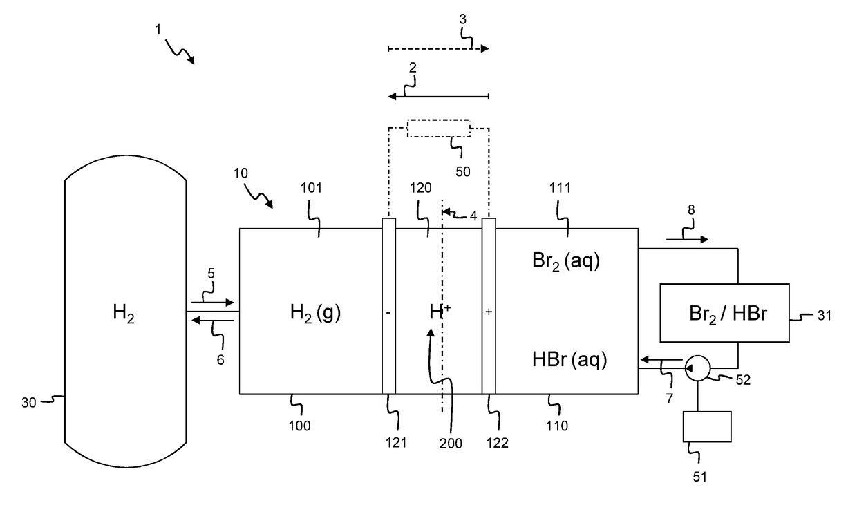
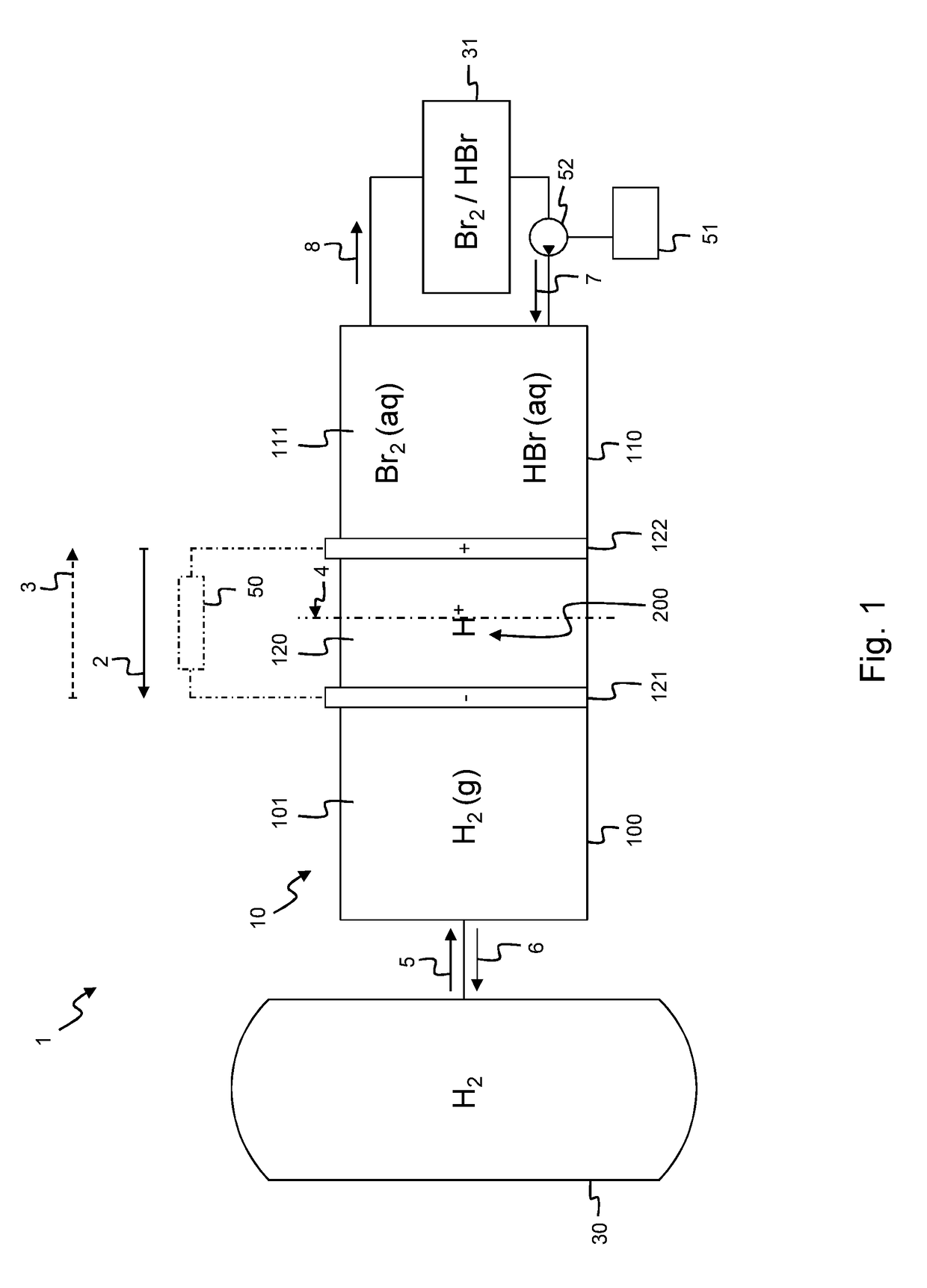
[0081]According to an embodiment shown in FIG. 1, a flow battery assembly 1 comprises a battery cell 10 comprising a hydrogen chamber 100, an electrolyte chamber 110. In between the hydrogen chamber 100 and the electrolyte chamber 110 there is positioned a membrane 123 of a membrane electrode assembly 120 which further comprises a hydrogen electrode 121 and an electrolyte electrode 122. In an alternative embodiment, the flow battery assembly 1 comprises a plurality of battery cells 10 similar to the battery cell 10 depicted in FIG. 1, as will be explained in further detail below with reference to the embodiment of FIG. 5. As shown, the planar membrane 123 comprises a central plane 4. The hydrogen electrode 121 is positioned on one side of the central plane 4 and the electrolyte electrode 122 is positioned on the opposite side of the central plane 4. As shown the hydrogen electrode 121 is positioned at the same side of the central plane 4 as the hydrogen chamber 100; while the elect...


PUM

PropertyMeasurementUnit
pressureaaaaaaaaaa
pressureaaaaaaaaaa
pressureaaaaaaaaaa

Abstract

A hydrogen-redox flow battery assembly comprising one or more battery cells. Each battery cell comprising: a hydrogen chamber, an electrolyte chamber, a membrane electrode assembly positioned between said hydrogen chamber and said electrolyte chamber, a hydrogen reservoir and an electrolyte reservoir. Wherein said hydrogen-redox flow battery assembly is further configured to allow an uncontrolled pressure difference between the pressure in said hydrogen chamber and the pressure in said electrolyte chamber. Wherein said pressure difference is determined by a diffusion of protons through said membrane electrode assembly during a charge and / or a discharge operation and said one or more battery cells of said hydrogen-redox flow battery assembly is / are completely positioned in said hydrogen reservoir.

Description

FIELD OF THE INVENTION[0001]The present invention generally relates to a flow battery assembly used to electrochemically generate and store electric power, especially to a flow battery assembly in which both charging and discharging reactions happen in the presence of hydrogen and of an electrolyte comprising a halogen ion or a mixture of halogen ions.BACKGROUND OF THE INVENTION[0002]Solar or wind energy-based systems as well as flow batteries provide solutions to the ever increasing need for the low cost generation and storage of electricity. A flow battery that uses hydrogen and a halogen ion, such as for example bromine, as active materials was invented in 1961 by the National Aeronautics and Space Administration. This type of flow battery demonstrates a high power density, i.e. it can store or release a high power per unit of membrane area. A flow battery relying on hydrogen and a halogen ion can indeed reach a power density of 10 kW·m−2, which is 20 times higher than the power ...

Claims


Application Information

Patent Timeline
Patent Type & Authority Applications(United States)
IPC IPC(8): H01M8/18H01M8/04186H01M8/04089H01M8/08
CPCH01M8/188H01M8/04089H01M8/04186H01M8/08H01M8/20H01M4/8605Y02E60/50
Inventor KOUT, WIEBRAND
Owner ELESTOR BV
Why Eureka
Try Eureka